User Manual
Page 3
Contents Notices...v Safety information...vi About this guide...vii AT4NM10T-I specifications summary...viii Chapter 1: 1.1 1.2 Before you proceed...1-1 Motherboard overview...1-2 1.2.1 1.2.2 Motherboard layout...1-2 Layout contents...1-2 Product introduction 1.3 1.4 Central Processing Unit (CPU... an operating system...1-17 Support DVD information...1-17 1.8 Software support...1-17 Chapter 2: 2.1 Managing and updating your BIOS...2-1 2.1.1 2.1.2 2.1.3 ASUS Update utility...2-1 ASUS EZ Flash 2...2-2 ASUS CrashFree BIOS...2-3 BIOS information 2.2 BIOS setup program...2-4 iii
Contents Notices...v Safety information...vi About this guide...vii AT4NM10T-I specifications summary...viii Chapter 1: 1.1 1.2 Before you proceed...1-1 Motherboard overview...1-2 1.2.1 1.2.2 Motherboard layout...1-2 Layout contents...1-2 Product introduction 1.3 1.4 Central Processing Unit (CPU... an operating system...1-17 Support DVD information...1-17 1.8 Software support...1-17 Chapter 2: 2.1 Managing and updating your BIOS...2-1 2.1.1 2.1.2 2.1.3 ASUS Update utility...2-1 ASUS EZ Flash 2...2-2 ASUS CrashFree BIOS...2-3 BIOS information 2.2 BIOS setup program...2-4 iii
User Manual
Page 8
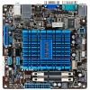
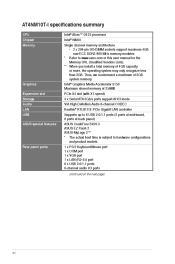
AT4NM10T-I specifications summary CPU Chipset Memory Intel® Atom™ D425 processor Intel® NM10 Single channel memory architecture - 2 x 204-pin SO-DIMM sockets support maximum 4GB non-ECC DDR3 800 MHz memory modules * Refer to www.asus.com or this user manual for... Realtek® RTL8111E PCIe Gigabit LAN controller Supports up to 8 USB 2.0/1.1 ports (2 ports at mid-board, 6 ports at back panel) ASUS CrashFree BIOS 3 ASUS EZ Flash 2 ASUS MyLogo 2™ * The actual boot time is subject to hardware configurations and product models. 1 x PS/2 Keyboard/Mouse port 1 x COM...
AT4NM10T-I specifications summary CPU Chipset Memory Intel® Atom™ D425 processor Intel® NM10 Single channel memory architecture - 2 x 204-pin SO-DIMM sockets support maximum 4GB non-ECC DDR3 800 MHz memory modules * Refer to www.asus.com or this user manual for... Realtek® RTL8111E PCIe Gigabit LAN controller Supports up to 8 USB 2.0/1.1 ports (2 ports at mid-board, 6 ports at back panel) ASUS CrashFree BIOS 3 ASUS EZ Flash 2 ASUS MyLogo 2™ * The actual boot time is subject to hardware configurations and product models. 1 x PS/2 Keyboard/Mouse port 1 x COM...
User Manual
Page 9
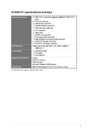
AT4NM10T-I specifications summary Internal connectors 1 x USB 2.0/1.1 connector supports additional 2 USB 2.0/1.1 ports 1 x CPU fan connector 1 x Chassis fan connector 1 x Chassis intrusion connector 1 x TPM connector (optional) 1 x LPT ...Flash ROM, AMI BIOS, PnP, DMI2.0, WfM2.0, SMBIOS 2.5 2 x Serial ATA cable 1 x I/O shield 1 x User Manual BIOS features Accessories Support DVD contents Form Factor Drivers ASUS PC Probe II ASUS Update Anti-virus software (OEM version) Mini ITX form factor: 6.7 in x 6.7 in (17cm x 17cm) * Specifications are subject to change without notice. ix
AT4NM10T-I specifications summary Internal connectors 1 x USB 2.0/1.1 connector supports additional 2 USB 2.0/1.1 ports 1 x CPU fan connector 1 x Chassis fan connector 1 x Chassis intrusion connector 1 x TPM connector (optional) 1 x LPT ...Flash ROM, AMI BIOS, PnP, DMI2.0, WfM2.0, SMBIOS 2.5 2 x Serial ATA cable 1 x I/O shield 1 x User Manual BIOS features Accessories Support DVD contents Form Factor Drivers ASUS PC Probe II ASUS Update Anti-virus software (OEM version) Mini ITX form factor: 6.7 in x 6.7 in (17cm x 17cm) * Specifications are subject to change without notice. ix

User Manual
Page 11
... cause severe damage to indicate that the system is detached from the power supply. If any motherboard component. Refer to page ix for buying an ASUS® AT4NM10T-I Onboard LED 1-1 Chapter 1: Product introduction The illustration below shows the location of the onboard LED. This is a reminder that you must shut down the... retailer. 1.1 Before you install or remove any component, ensure that came with a standby power LED that lights up to the motherboard, peripherals, or components. SB_PWR AT4NM10T-I ON Standby Power OFF Powered Off...
... cause severe damage to indicate that the system is detached from the power supply. If any motherboard component. Refer to page ix for buying an ASUS® AT4NM10T-I Onboard LED 1-1 Chapter 1: Product introduction The illustration below shows the location of the onboard LED. This is a reminder that you must shut down the... retailer. 1.1 Before you install or remove any component, ensure that came with a standby power LED that lights up to the motherboard, peripherals, or components. SB_PWR AT4NM10T-I ON Standby Power OFF Powered Off...
User Manual
Page 12
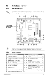
...so can damage the motherboard. 1.2.2 1. 2. 3. 4. 5. 6. 7. 8. 9. LPT DDR3 SO-DIMM_A2 (64bit, 204-pin module) Super I/O USB34 AT4NM10T-I 1-2 The edge with external ports goes to the chassis. DO NOT overtighten the screws! Layout contents Page 1-16 1-10 1-15 1-13 1-14 ...pin CHASSIS) Internal speaker connector (4-pin SPEAKER) Digital audio connector (4-1 pin SPDIF_OUT) 1-15 1-8 Front panel audio connector (10-1 pin AAFP) 1-13 ASUS AT4NM10T-I 17.0cm(6.7in) LAN1_USB12 RTL 8111E Intel® NM10 SB_PWR 2 8 9 8Mb BIOS AUDIO AAFP VIA VT1705 Lithium Cell CMOS Power JMB 362 SATA3G_E2...
...so can damage the motherboard. 1.2.2 1. 2. 3. 4. 5. 6. 7. 8. 9. LPT DDR3 SO-DIMM_A2 (64bit, 204-pin module) Super I/O USB34 AT4NM10T-I 1-2 The edge with external ports goes to the chassis. DO NOT overtighten the screws! Layout contents Page 1-16 1-10 1-15 1-13 1-14 ...pin CHASSIS) Internal speaker connector (4-pin SPEAKER) Digital audio connector (4-1 pin SPDIF_OUT) 1-15 1-8 Front panel audio connector (10-1 pin AAFP) 1-13 ASUS AT4NM10T-I 17.0cm(6.7in) LAN1_USB12 RTL 8111E Intel® NM10 SB_PWR 2 8 9 8Mb BIOS AUDIO AAFP VIA VT1705 Lithium Cell CMOS Power JMB 362 SATA3G_E2...
User Manual
Page 14
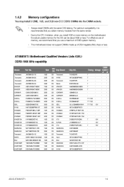
...-15A KFC8FNMXF-BXX-15A KFC8FNMXF-BXX-15A D1288JPPDPGD9U J1108BDSE-DJ-F D1288JPNDPLD9U K4B1G0846E K4B1G0846F TK243PDF3 H5TQ1G83AFPH9C N2CB1616AP-BE IDSH1G-04A1F1C-10F K4B1G16460-HCF8 H5TQ1G83BFRG7C 7 7 7 7 7 7 - Memory configurations AT4NM10T-I 1-4 ASUS AT4NM10T-I Motherboard Qualified Vendors Lists (QVL) DDR3-1066 MHz capability Vendor Transcend Transcend Transcend Transcend APACER APACER CORSAIR CORSAIR G.SKILL G.SKILL GEIL HYNIX KINGMAX KINGMAX KINGMAX...
...-15A KFC8FNMXF-BXX-15A KFC8FNMXF-BXX-15A D1288JPPDPGD9U J1108BDSE-DJ-F D1288JPNDPLD9U K4B1G0846E K4B1G0846F TK243PDF3 H5TQ1G83AFPH9C N2CB1616AP-BE IDSH1G-04A1F1C-10F K4B1G16460-HCF8 H5TQ1G83BFRG7C 7 7 7 7 7 7 - Memory configurations AT4NM10T-I 1-4 ASUS AT4NM10T-I Motherboard Qualified Vendors Lists (QVL) DDR3-1066 MHz capability Vendor Transcend Transcend Transcend Transcend APACER APACER CORSAIR CORSAIR G.SKILL G.SKILL GEIL HYNIX KINGMAX KINGMAX KINGMAX...
User Manual
Page 16
Keep the screw for information on BIOS setup. PCI Express x4 slots ASUS AT4NM10T-I 1-6 Remove the bracket opposite the slot that comply with the slot and press firmly until the card is already installed in a chassis). Replace the system ...
Keep the screw for information on BIOS setup. PCI Express x4 slots ASUS AT4NM10T-I 1-6 Remove the bracket opposite the slot that comply with the slot and press firmly until the card is already installed in a chassis). Replace the system ...
User Manual
Page 18
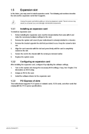
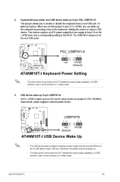
... or using a USB device. USB device wake-up (3-pin USBPW7-8) USBPW78 AT4NM10T-I 1 2 2 3 +5V (Default) +5VSB AT4NM10T-I USB Device Wake Up • The USB device wake-up feature. ASUS AT4NM10T-I Keyboard Power Setting The total current consumed must NOT exceed the power supply capability...5VSB lead, and a corresponding setting in sleep mode. This jumper allows you can wake up (3-pin PS2_USBPW1-6) PS2_USBPW1-6 1 AT4NM10T-I 2 2 3 +5V +5VSB (Default) AT4NM10T-I 1-8 The USBPW1-6 jumper is for each USB port; 2. Keyboard/mouse power and USB device wake-up the computer ...
... or using a USB device. USB device wake-up (3-pin USBPW7-8) USBPW78 AT4NM10T-I 1 2 2 3 +5V (Default) +5VSB AT4NM10T-I USB Device Wake Up • The USB device wake-up feature. ASUS AT4NM10T-I Keyboard Power Setting The total current consumed must NOT exceed the power supply capability...5VSB lead, and a corresponding setting in sleep mode. This jumper allows you can wake up (3-pin PS2_USBPW1-6) PS2_USBPW1-6 1 AT4NM10T-I 2 2 3 +5V +5VSB (Default) AT4NM10T-I 1-8 The USBPW1-6 jumper is for each USB port; 2. Keyboard/mouse power and USB device wake-up the computer ...
User Manual
Page 20
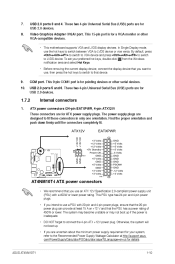
...plugs. This 9-pin COM1 port is inadequate. • DO NOT forget to connect the 4-pin ATX +12V power plug. USB 2.0 ports 5 and 6. ASUS AT4NM10T-I AT4NM10T-I ATX power connectors • We recommend that you intend to use , then press the hot keys to switch to the Recommended Power Supply Wattage Calculator...GND -12 Volts +3 Volts +3 Volts +12 Volts +12 Volts +5V Standby Power OK PIN 1 GND +5 Volts GND +5 Volts GND +3 Volts +3 Volts PIN 1 AT4NM10T-I GND GND 1-10 The system may become unstable or may not boot up . • If you want to LVDS device or vice versa. These two...
...plugs. This 9-pin COM1 port is inadequate. • DO NOT forget to connect the 4-pin ATX +12V power plug. USB 2.0 ports 5 and 6. ASUS AT4NM10T-I AT4NM10T-I ATX power connectors • We recommend that you intend to use , then press the hot keys to switch to the Recommended Power Supply Wattage Calculator...GND -12 Volts +3 Volts +3 Volts +12 Volts +12 Volts +5V Standby Power OK PIN 1 GND +5 Volts GND +5 Volts GND +3 Volts +3 Volts PIN 1 AT4NM10T-I GND GND 1-10 The system may become unstable or may not boot up . • If you want to LVDS device or vice versa. These two...
User Manual
Page 22
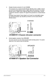
... cap. Chassis intrusion connector (4-1 pin CHASSIS) CHASSIS Chassis Signal GND +5VSB_MB PIN 1 AT4NM10T-I 1-12 Remove the jumper caps only when you to use the chassis intrusion detection feature. Internal speaker connector (4-pin SPEAKER) AT4NM10T-I SPEAKER +5V GND GND Speaker Out AT4NM10T-I Speaker Out Connector ASUS AT4NM10T-I AT4NM10T-I Chassis intrusion connector 5. This connector is removed or replaced. 4.
... cap. Chassis intrusion connector (4-1 pin CHASSIS) CHASSIS Chassis Signal GND +5VSB_MB PIN 1 AT4NM10T-I 1-12 Remove the jumper caps only when you to use the chassis intrusion detection feature. Internal speaker connector (4-pin SPEAKER) AT4NM10T-I SPEAKER +5V GND GND Speaker Out AT4NM10T-I Speaker Out Connector ASUS AT4NM10T-I AT4NM10T-I Chassis intrusion connector 5. This connector is removed or replaced. 4.
User Manual
Page 23
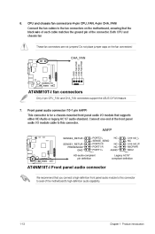
...R NC PORT1 R NC PORT1 L AGND Line out_L NC Line out_R MICPWR MIC2 AT4NM10T-I PIN 1 PIN 1 HD-audio-compliant pin definition Legacy AC'97 compliant definition AT4NM10T-I fan connectors Only 4-pin CPU_FAN and CHA_FAN connectors support the ASUS Q-FAN feature. 7. CPU and chassis fan connectors (4-pin CPU_FAN, 4-pin CHA_FAN...) CHA_FAN GND CHA FAN PWR CHA FAN IN CHA FAN PWM CPU_FAN GND CPU FAN PWR CPU FAN IN CPU FAN PWM AT4NM10T-I Front panel audio connector We ...
...R NC PORT1 R NC PORT1 L AGND Line out_L NC Line out_R MICPWR MIC2 AT4NM10T-I PIN 1 PIN 1 HD-audio-compliant pin definition Legacy AC'97 compliant definition AT4NM10T-I fan connectors Only 4-pin CPU_FAN and CHA_FAN connectors support the ASUS Q-FAN feature. 7. CPU and chassis fan connectors (4-pin CPU_FAN, 4-pin CHA_FAN...) CHA_FAN GND CHA FAN PWR CHA FAN IN CHA FAN PWM CPU_FAN GND CPU FAN PWR CPU FAN IN CPU FAN PWM AT4NM10T-I Front panel audio connector We ...
User Manual
Page 24
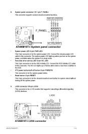
...this connector. LVDS GND VCC VCC GND VEEDID LCD_PID0 LCD_PID1 LDDC_CS# DDC DATA DDC CLK VLED VLED VLED VLED VLED_GND AT4NM10T-I AT4NM10T-I LVDS connector ASUS AT4NM10T-I System panel connector • This 2-pin connector is for system reboot without turning off button (2-pin PWRBTN) This ... HDD Activity LED. LVDS connector (30-pin LVDS) 9. PWR LED PWR BTN System panel connector (10-1 pin F_PANEL) F_PANEL AT4NM10T-I PIN 1 HD_LED AT4NM10T-I 1-14 BLIM BL_ON GND DATA_0DATA_0+ GDN DATA_1DATA_1+ GND DATA_2DATA_2+ GND CLKCLK+ GND PIN 1 HD_LED+ HD_LEDGround Reset RESET PLED+ ...
...this connector. LVDS GND VCC VCC GND VEEDID LCD_PID0 LCD_PID1 LDDC_CS# DDC DATA DDC CLK VLED VLED VLED VLED VLED_GND AT4NM10T-I AT4NM10T-I LVDS connector ASUS AT4NM10T-I System panel connector • This 2-pin connector is for system reboot without turning off button (2-pin PWRBTN) This ... HDD Activity LED. LVDS connector (30-pin LVDS) 9. PWR LED PWR BTN System panel connector (10-1 pin F_PANEL) F_PANEL AT4NM10T-I PIN 1 HD_LED AT4NM10T-I 1-14 BLIM BL_ON GND DATA_0DATA_0+ GDN DATA_1DATA_1+ GND DATA_2DATA_2+ GND CLKCLK+ GND PIN 1 HD_LED+ HD_LEDGround Reset RESET PLED+ ...

User Manual
Page 26
LPT connector (26-1 pin LPT) The LPT (Line Printing Terminal) connector supports devices such as IEEE 1284, which is the parallel port interface on IBM PC-compatible computers. LPT GND GND GND GND GND GND GND GND SLIN# INIT# ERR# AFD SLCT PE BUSY ACK# PD7 PD6 PD5 PD4 PD3 PD2 PD1 PD0 STB# PIN 1 AT4NM10T-I Parallel Port Connector ASUS AT4NM10T-I AT4NM10T-I 1-16 LPT standardizes as a printer. 12.
LPT connector (26-1 pin LPT) The LPT (Line Printing Terminal) connector supports devices such as IEEE 1284, which is the parallel port interface on IBM PC-compatible computers. LPT GND GND GND GND GND GND GND GND SLIN# INIT# ERR# AFD SLCT PE BUSY ACK# PD7 PD6 PD5 PD4 PD3 PD2 PD1 PD0 STB# PIN 1 AT4NM10T-I Parallel Port Connector ASUS AT4NM10T-I AT4NM10T-I 1-16 LPT standardizes as a printer. 12.
User Manual
Page 29
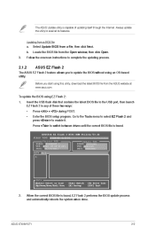
...the BIOS update process and automatically reboots the system when done. Before you to complete the updating process. 2.1.2 The ASUS EZ Flash 2 feature allows you start using EZ Flash 2: 1. ASUS EZ Flash 2 To update the BIOS using this utility, download the latest BIOS file from a BIOS file a. ...to enable it. Select Update BIOS from the Open window, then click Open. Enter the BIOS setup program. When the correct BIOS file is found . ASUS AT4NM10T-I VER: 0306 (H:00 B:02) DATE: 02/23/2011 A: Update ROM BOARD: Unknown VER: Unknown DATE: Unknown PATH: A:\ Note [Enter] Select ...
...the BIOS update process and automatically reboots the system when done. Before you to complete the updating process. 2.1.2 The ASUS EZ Flash 2 feature allows you start using EZ Flash 2: 1. ASUS EZ Flash 2 To update the BIOS using this utility, download the latest BIOS file from a BIOS file a. ...to enable it. Select Update BIOS from the Open window, then click Open. Enter the BIOS setup program. When the correct BIOS file is found . ASUS AT4NM10T-I VER: 0306 (H:00 B:02) DATE: 02/23/2011 A: Update ROM BOARD: Unknown VER: Unknown DATE: Unknown PATH: A:\ Note [Enter] Select ...

User Manual
Page 31
...shut down the system properly from a running operating system can cause damage to turn the system off then back on the system chassis. ASUS AT4NM10T-I 2-4 Do this motherboard. Select the Load Setups Default item under the Exit Menu. Entering BIOS Setup at startup To enter BIOS Setup ...at www.asus.com to force reset from the operating system. • The default BIOS settings for this section are for reference purposes only, and...
...shut down the system properly from a running operating system can cause damage to turn the system off then back on the system chassis. ASUS AT4NM10T-I 2-4 Do this motherboard. Select the Load Setups Default item under the Exit Menu. Entering BIOS Setup at startup To enter BIOS Setup ...at www.asus.com to force reset from the operating system. • The default BIOS settings for this section are for reference purposes only, and...
User Manual
Page 33
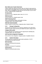
.... System Memory Displays the auto-detected system memory. When set to [Auto], the data transfer from and to the device occurs multiple sectors at a time. ASUS AT4NM10T-I 2-6 When set or change the configurations for the Serial ATA connectors supported by the Southbridge chip. The BIOS automatically detects the items in this menu...
.... System Memory Displays the auto-detected system memory. When set to [Auto], the data transfer from and to the device occurs multiple sectors at a time. ASUS AT4NM10T-I 2-6 When set or change the configurations for the Serial ATA connectors supported by the Southbridge chip. The BIOS automatically detects the items in this menu...
User Manual
Page 35
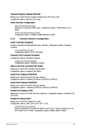
... from LVDS only or both. Configuration options: [Disabled] [378] [278] [3BC] Allows you to select the Serial Port2 base address. Configuration options: [DMA0] [DMA1] [DMA3] ASUS AT4NM10T-I 2-8 Configuration options: [Disabled] [IDE Mode] Serial Port1 Address [3F8/IRQ4] Serial Port2 Address [2F8/IRQ3] Parallel Port Address [378] Parallel Port Mode [SSP] Allows you...
... from LVDS only or both. Configuration options: [Disabled] [378] [278] [3BC] Allows you to select the Serial Port2 base address. Configuration options: [DMA0] [DMA1] [DMA3] ASUS AT4NM10T-I 2-8 Configuration options: [Disabled] [IDE Mode] Serial Port1 Address [3F8/IRQ4] Serial Port2 Address [2F8/IRQ3] Parallel Port Address [378] Parallel Port Mode [SSP] Allows you...
User Manual
Page 37
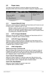
... power than in the RSDT pointer list. When this item is included in the S1 state. Configuration options: [Disabled] [Enabled] ASUS AT4NM10T-I BIOS Setup Boot Tools Exit [S3 only] [Disabled] [Enabled] [Disabled] Version 0306 Select the ACPI state used for System Suspend. Main ...Advanced Power AT4NM10T-I 2-10 When set to generate a wake event. Configuration options: [Disabled] [Enabled] Power On By Ring [Disabled] Allows you to enable...
... power than in the RSDT pointer list. When this item is included in the S1 state. Configuration options: [Disabled] [Enabled] ASUS AT4NM10T-I BIOS Setup Boot Tools Exit [S3 only] [Disabled] [Enabled] [Disabled] Version 0306 Select the ACPI state used for System Suspend. Main ...Advanced Power AT4NM10T-I 2-10 When set to generate a wake event. Configuration options: [Disabled] [Enabled] Power On By Ring [Disabled] Allows you to enable...
User Manual
Page 39
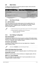
...menu items allow you to use the ASUS MyLogo2™ feature. Configuration options: [Disabled] [Enabled] Set this item allows the BIOS to skip some power on state for the NumLock. Configuration options: [Disabled] [Enabled] ASUS AT4NM10T-I BIOS Setup Boot Tools Exit Version ...0306 Specifies the Boot Device Priority sequence. Main Advanced Power AT4NM10T-I 2-12 When set to [Disabled], BIOS performs all the POST items. Configuration options...
...menu items allow you to use the ASUS MyLogo2™ feature. Configuration options: [Disabled] [Enabled] Set this item allows the BIOS to skip some power on state for the NumLock. Configuration options: [Disabled] [Enabled] ASUS AT4NM10T-I BIOS Setup Boot Tools Exit Version ...0306 Specifies the Boot Device Priority sequence. Main Advanced Power AT4NM10T-I 2-12 When set to [Disabled], BIOS performs all the POST items. Configuration options...

User Manual
Page 41
...Flash 2 2.7.1 Allows you press , a confirmation message appears. See section 2.1.2 ASUS EZ Flash 2 for details. When set to [Setup], BIOS checks for user password when accessing the Setup utility. Main Advanced Power AT4NM10T-I 2-14 Use the left/right arrow key to select between [Yes] or... [Setup] [Always] 2.7 Tools menu The Tools menu items allow you set your choice. ASUS EZ Flash 2 ASUS AT4NM10T-I BIOS Setup Boot Tools Exit Version 0306 Press ENTER to run ASUS EZ Flash 2. The message Password Installed appears after you to configure options for special functions. ...
...Flash 2 2.7.1 Allows you press , a confirmation message appears. See section 2.1.2 ASUS EZ Flash 2 for details. When set to [Setup], BIOS checks for user password when accessing the Setup utility. Main Advanced Power AT4NM10T-I 2-14 Use the left/right arrow key to select between [Yes] or... [Setup] [Always] 2.7 Tools menu The Tools menu items allow you set your choice. ASUS EZ Flash 2 ASUS AT4NM10T-I BIOS Setup Boot Tools Exit Version 0306 Press ENTER to run ASUS EZ Flash 2. The message Password Installed appears after you to configure options for special functions. ...


