
AP140R User Manual English Edition
Page 6
...Fax: General Email: 150 Li-Te Road, Peitou, Taipei, Taiwan 112 +886-2-2894-3447 +886-2-2894-3449 info@asus.com.tw Technical Support MB/Others (Tel): Notebook (Tel): Desktop/Server (Tel): Support Fax: Support Email: Web Site: Newsgroup: +886-2-2890-7121 (English) +886-2-2890-7122 (...English) +886-2-2890-7123 (English) +886-2-2890-7698 tsd@asus.com.tw www.asus.com.tw cscnews.asus.com.tw ASUS COMPUTER INTERNATIONAL (America) Address: General ...
...Fax: General Email: 150 Li-Te Road, Peitou, Taipei, Taiwan 112 +886-2-2894-3447 +886-2-2894-3449 info@asus.com.tw Technical Support MB/Others (Tel): Notebook (Tel): Desktop/Server (Tel): Support Fax: Support Email: Web Site: Newsgroup: +886-2-2890-7121 (English) +886-2-2890-7122 (...English) +886-2-2890-7123 (English) +886-2-2890-7698 tsd@asus.com.tw www.asus.com.tw cscnews.asus.com.tw ASUS COMPUTER INTERNATIONAL (America) Address: General ...

AP140R User Manual English Edition
Page 8
Place the server on this server must be conducted by yourself. Operation Safety IMPORTANT • Any mechanical operation on a stable surface. 8 If any additional devices to or from the system, ensure ... product is broken, do not try to fix it by certified or experienced engineers. • Before operating the server, carefully read all the manuals included with the server package. • Before using the server, make sure all cables are correctly connected and the power cables are connected. If possible, disconnect all power cables...
Place the server on this server must be conducted by yourself. Operation Safety IMPORTANT • Any mechanical operation on a stable surface. 8 If any additional devices to or from the system, ensure ... product is broken, do not try to fix it by certified or experienced engineers. • Before operating the server, carefully read all the manuals included with the server package. • Before using the server, make sure all cables are correctly connected and the power cables are connected. If possible, disconnect all power cables...
AP140R User Manual English Edition
Page 9
About This Manual Introduction "About This Manual" introduces the contents of information that are not contained in this document. AP140R Server User's Manual 9 It also lists other sources of this manual. This part includes the target audience, chapter description, and conventions used.
About This Manual Introduction "About This Manual" introduces the contents of information that are not contained in this document. AP140R Server User's Manual 9 It also lists other sources of this manual. This part includes the target audience, chapter description, and conventions used.
AP140R User Manual English Edition
Page 10
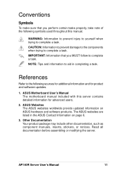
...: Introduction: About This Manual This part introduces the contents of the server. It includes the target audience, chapter description, and conventions used. It includes sections on configuring an entry-level server. Appendix A: Power Supply Information This appendix gives information on the 200...that you may refer to this manual. Audience This installation guide is intended for system integrators, and experienced users with the server. It also lists other sources of the problems and offers solutions. Chapter 3: Hardware Options This chapter describes optional hardware ...
...: Introduction: About This Manual This part introduces the contents of the server. It includes the target audience, chapter description, and conventions used. It includes sections on configuring an entry-level server. Appendix A: Power Supply Information This appendix gives information on the 200...that you may refer to this manual. Audience This installation guide is intended for system integrators, and experienced users with the server. It also lists other sources of the problems and offers solutions. Chapter 3: Hardware Options This chapter describes optional hardware ...
AP140R User Manual English Edition
Page 11
... may include other documentation, such as component manuals, inserts, stickers, or notices. AP140R Server User's Manual 11 ASUS Motherboard User's Manual The motherboard manual included with this manual. IMPORTANT: Information that you MUST follow to aid in the ASUS Contact Information on ASUS hardware and software products. NOTE: Tips and information to complete a task. CAUTION...
... may include other documentation, such as component manuals, inserts, stickers, or notices. AP140R Server User's Manual 11 ASUS Motherboard User's Manual The motherboard manual included with this manual. IMPORTANT: Information that you MUST follow to aid in the ASUS Contact Information on ASUS hardware and software products. NOTE: Tips and information to complete a task. CAUTION...
AP140R User Manual English Edition
Page 12
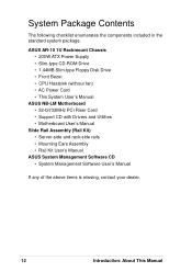
...Slim-type Floppy Disk Drive • Front Bezel • CPU Heatsink (without fan) • AC Power Cord • This System User's Manual ASUS NB-LM Motherboard • 32-bit/33MHz PCI Riser Card • Support CD with Drivers and Utilities • Motherboard User's Manual Slide Rail ...Assembly (Rail Kit) • Server-side and rack-side rails • Mounting Ears Assembly • Rail Kit User's Manual ASUS System Management Software CD • System Management Software User's Manual If any of the above items ...
...Slim-type Floppy Disk Drive • Front Bezel • CPU Heatsink (without fan) • AC Power Cord • This System User's Manual ASUS NB-LM Motherboard • 32-bit/33MHz PCI Riser Card • Support CD with Drivers and Utilities • Motherboard User's Manual Slide Rail ...Assembly (Rail Kit) • Server-side and rack-side rails • Mounting Ears Assembly • Rail Kit User's Manual ASUS System Management Software CD • System Management Software User's Manual If any of the above items ...
AP140R User Manual English Edition
Page 13
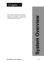
This includes sections on front panel, rear panel, and internal features of the server. System Overview AP140R Server User's Manual 13 Chapter 1 This chapter describes the general features of the server.
This includes sections on front panel, rear panel, and internal features of the server. System Overview AP140R Server User's Manual 13 Chapter 1 This chapter describes the general features of the server.
AP140R User Manual English Edition
Page 14
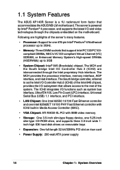
...14 Chapter 1: System Overview The MCH and the South bridge Intel I/O Controller Hub 2 (ICH2) are highlights of the system. The server is a 1U rackmount form factor that support Intel PC133/PC100compliant DIMMs, NEC's VC133-compliant Virtual Channel (VC) SDRAM, or Enhanced ...174; Pentium® 4 Northwood processor up to 3GB • System Chipset: Intel® 845 (Brookdale) chipset. 1.1 System Features The ASUS AP140R Server is powered by Intel® Pentium® 4 processor, and supports the latest I/O and video technologies through the Intel proprietary Hub interface. ...
...14 Chapter 1: System Overview The MCH and the South bridge Intel I/O Controller Hub 2 (ICH2) are highlights of the system. The server is a 1U rackmount form factor that support Intel PC133/PC100compliant DIMMs, NEC's VC133-compliant Virtual Channel (VC) SDRAM, or Enhanced ...174; Pentium® 4 Northwood processor up to 3GB • System Chipset: Intel® 845 (Brookdale) chipset. 1.1 System Features The ASUS AP140R Server is powered by Intel® Pentium® 4 processor, and supports the latest I/O and video technologies through the Intel proprietary Hub interface. ...
AP140R User Manual English Edition
Page 15
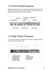
PS/2 Keyboard Port 3. PS/2 Mouse Port 4. 1.2 Front Panel Features The front panel of the server allows easy access to the floppy, CDROM, and hard disk drives. The power button and the system LED indicators are also located on the ... Drive Hard Drive Bay 0 Hard Drive Bay 1 Hard Drive Bay 2 1.3 Rear Panel Features The server rear panel includes the connectors the system devices and a slot for an expansion card. 1 2 3 45 6 7 8 9 1. AC Power Connector 2. VGA Port 7. Expansion Slot AP140R Server User's Manual 15 LAN1 Port (RJ-45) 8. LAN2 Port (RJ-45) 9. USB Ports 1 ...
PS/2 Keyboard Port 3. PS/2 Mouse Port 4. 1.2 Front Panel Features The front panel of the server allows easy access to the floppy, CDROM, and hard disk drives. The power button and the system LED indicators are also located on the ... Drive Hard Drive Bay 0 Hard Drive Bay 1 Hard Drive Bay 2 1.3 Rear Panel Features The server rear panel includes the connectors the system devices and a slot for an expansion card. 1 2 3 45 6 7 8 9 1. AC Power Connector 2. VGA Port 7. Expansion Slot AP140R Server User's Manual 15 LAN1 Port (RJ-45) 8. LAN2 Port (RJ-45) 9. USB Ports 1 ...

AP140R User Manual English Edition
Page 16
...-Wire IDE Cable 11. Riser Card Holder 14. Central Processing Unit (Optional) 16 Chapter 1: System Overview The picture below shows the standard components of the server. 1 23 4 15 14 13 12 11 10 5 (Top) 6 (Bottom) 7 8 (Top) 9 (Bottom) 1. Power Supply 2. Floppy Drive 6. Memory Modules...Optional) 15. Power Supply Fan 3. Floppy Ribbon Cable 5. Slim CD-ROM Drive 9. 1.4 Internal Features The standard components inside the server include the motherboard, power supply, floppy and CD-ROM drives, and cables. Hard Disk Drive Bay 2 7. Chassis Fans 12. Motherboard 13.
...-Wire IDE Cable 11. Riser Card Holder 14. Central Processing Unit (Optional) 16 Chapter 1: System Overview The picture below shows the standard components of the server. 1 23 4 15 14 13 12 11 10 5 (Top) 6 (Bottom) 7 8 (Top) 9 (Bottom) 1. Power Supply 2. Floppy Drive 6. Memory Modules...Optional) 15. Power Supply Fan 3. Floppy Ribbon Cable 5. Slim CD-ROM Drive 9. 1.4 Internal Features The standard components inside the server include the motherboard, power supply, floppy and CD-ROM drives, and cables. Hard Disk Drive Bay 2 7. Chassis Fans 12. Motherboard 13.
AP140R User Manual English Edition
Page 17
Hardware Setup AP140R Server User's Manual 17 Chapter 2 This chapter describes the hardware setup procedures that you have to perform when installing system components.
Hardware Setup AP140R Server User's Manual 17 Chapter 2 This chapter describes the hardware setup procedures that you have to perform when installing system components.

AP140R User Manual English Edition
Page 19
Rear Panel Motherboard Screws Note Place six (6) screws in the holes indicated by circles to secure the motherboard to the rear part of the server are already installed as indicated in section "1.4 Internal Features". Do not overtighten the screws. 2.2 Motherboard Placement NOTE The motherboard and other ...the chassis correctly. Note: This corner screw hole is used to the motherboard user's manual for detailed technical information about the motherboard. AP140R Server User's Manual 19 Refer to secure the fan partition bracket. Doing so may damage the motherboard.
Rear Panel Motherboard Screws Note Place six (6) screws in the holes indicated by circles to secure the motherboard to the rear part of the server are already installed as indicated in section "1.4 Internal Features". Do not overtighten the screws. 2.2 Motherboard Placement NOTE The motherboard and other ...the chassis correctly. Note: This corner screw hole is used to the motherboard user's manual for detailed technical information about the motherboard. AP140R Server User's Manual 19 Refer to secure the fan partition bracket. Doing so may damage the motherboard.

AP140R User Manual English Edition
Page 20
IMPORTANT The CPU heatsink must be installed to the server chassis underneath the motherboard. Connect the Fan Cable From the factory, the CPU fan cable is already connected to the 3-pin fan connector on top ...of the installed CPU matching the four screws to the holes around the socket. 2.3 Installing the 1U Heatsink CPU Heatsink The 1U server comes with a specially designed heatsink as shown here. Install the Heatsink Place the heatsink on the motherboard marked CPU_FAN. To secure the heatsink, tighten each...
IMPORTANT The CPU heatsink must be installed to the server chassis underneath the motherboard. Connect the Fan Cable From the factory, the CPU fan cable is already connected to the 3-pin fan connector on top ...of the installed CPU matching the four screws to the holes around the socket. 2.3 Installing the 1U Heatsink CPU Heatsink The 1U server comes with a specially designed heatsink as shown here. Install the Heatsink Place the heatsink on the motherboard marked CPU_FAN. To secure the heatsink, tighten each...

AP140R User Manual English Edition
Page 21
IDE Back Plane - Hard Drive Side IDE to the IDE back plane by swappable connectors. 2.4 Hard Drive Connector Boards The server comes with three externally accessible drive bays connected to Motherboard IDE Hard Drive Tray Connector IDE Hard Drive Tray Connector IDE Hard Drive Tray Connector Hard Drive Tray Board IDE Back Plane Side Hard Drive Tray Board Hard Drive Side AP140R Server User's Manual 21 IDE Connector Side Power In IDE to Motherboard IDE Back Plane -
IDE Back Plane - Hard Drive Side IDE to the IDE back plane by swappable connectors. 2.4 Hard Drive Connector Boards The server comes with three externally accessible drive bays connected to Motherboard IDE Hard Drive Tray Connector IDE Hard Drive Tray Connector IDE Hard Drive Tray Connector Hard Drive Tray Board IDE Back Plane Side Hard Drive Tray Board Hard Drive Side AP140R Server User's Manual 21 IDE Connector Side Power In IDE to Motherboard IDE Back Plane -

AP140R User Manual English Edition
Page 22
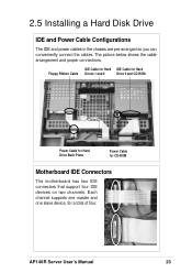
... the levers back into drive tray. 4. Due to release the tray, then pull the tray out of the drive bays is a removable tray for this server. Flip open the tray levers to mechanical issues, the drive tray's connector board may not fit some hard drives. Attach connector board to "Cable Select... fit the hard drive before purchasing. Set hard drive to drive. 6. Install the Hard Drive After the drive is "Master". 2.5 Installing a Hard Disk Drive The server comes with three externally accessible drive bays.
... the levers back into drive tray. 4. Due to release the tray, then pull the tray out of the drive bays is a removable tray for this server. Flip open the tray levers to mechanical issues, the drive tray's connector board may not fit some hard drives. Attach connector board to "Cable Select... fit the hard drive before purchasing. Set hard drive to drive. 6. Install the Hard Drive After the drive is "Master". 2.5 Installing a Hard Disk Drive The server comes with three externally accessible drive bays.
AP140R User Manual English Edition
Page 23
... power cables in the chassis are pre-arranged so you can conveniently connect the cables. The picture below shows the cable arrangement and proper connections. AP140R Server User's Manual 23 Each channel supports one master and one slave device, for CD-ROM Motherboard IDE Connectors The motherboard has two IDE connectors that...
... power cables in the chassis are pre-arranged so you can conveniently connect the cables. The picture below shows the cable arrangement and proper connections. AP140R Server User's Manual 23 Each channel supports one master and one slave device, for CD-ROM Motherboard IDE Connectors The motherboard has two IDE connectors that...

AP140R User Manual English Edition
Page 25
... to access the PCI riser card. 2. Remove the PCI Slot Cover from the rear panel. Locking Tab Riser Card Holder Riser Card PCI Slot Cover AP140R Server User's Manual 25 Lift up the Locking Tab beside the riser card holder. 3. A PCI riser card comes installed in this slot Install these golden fingers...
... to access the PCI riser card. 2. Remove the PCI Slot Cover from the rear panel. Locking Tab Riser Card Holder Riser Card PCI Slot Cover AP140R Server User's Manual 25 Lift up the Locking Tab beside the riser card holder. 3. A PCI riser card comes installed in this slot Install these golden fingers...

AP140R User Manual English Edition
Page 27
Chapter 3 This chapter describes optional hardware procedures that you may have to do when configuring the system. Hardware Options AP140R Server User's Manual 27
Chapter 3 This chapter describes optional hardware procedures that you may have to do when configuring the system. Hardware Options AP140R Server User's Manual 27

AP140R User Manual English Edition
Page 28
...-ROM drive is already installed in this section. On the other side of the slim CD-ROM drive. 3.1 Remove/Install a CD-ROM Drive The 1U server supports a slim CD-ROM drive. Two screw holes are available for securing the board to the instructions in the chassis.
...-ROM drive is already installed in this section. On the other side of the slim CD-ROM drive. 3.1 Remove/Install a CD-ROM Drive The 1U server supports a slim CD-ROM drive. Two screw holes are available for securing the board to the instructions in the chassis.

AP140R User Manual English Edition
Page 29
... is secured by four screws (two on the right shows the locations of the arrow in the above picture. 4. Remove these screws to the cage. AP140R Server User's Manual 29 Lift up the drive cage from the CD-ROM adapter board. Power Cable IDE Cable 3. Slide the CD-ROM drive cage outward...
... is secured by four screws (two on the right shows the locations of the arrow in the above picture. 4. Remove these screws to the cage. AP140R Server User's Manual 29 Lift up the drive cage from the CD-ROM adapter board. Power Cable IDE Cable 3. Slide the CD-ROM drive cage outward...
