
Motherboard DIY Troubleshooting Guide
Page 20
1.5.3 Motherboard-Layout PS/2KBMS T: Mouse B: Keyboard KBPWR ATX12V 21,1cm SPDIF_O CPU_FAN Socket 939 A8V-X DDR DIMM_A1 (64 bit,184-pin module) DDR DIMM_A2 (64 bit,184-pin module) DDR DIMM_B1 (64 bit,184-pin module) DDR DIMM_B2 (64 bit,... AUX CD AD1986A SPDIF_OUT AGP PCI1 ® PCI2 PCI3 VIA VT8251 SATA4 SATA2 ITE IT8712F-A GAME PCIEX1_1 PCIEX1_2 4Mbit BIOS CR2032 3V Lithium Cell CMOS Power FLOPPY USB56 USBPW5678 CLRTC SATA3 SATA1 CHA_FAN SB_PWR USB78 CHASISS PANEL PRI_IDE 30,5cm SEC_IDE 1-8 Kapitel 1: Produkteinführung
1.5.3 Motherboard-Layout PS/2KBMS T: Mouse B: Keyboard KBPWR ATX12V 21,1cm SPDIF_O CPU_FAN Socket 939 A8V-X DDR DIMM_A1 (64 bit,184-pin module) DDR DIMM_A2 (64 bit,184-pin module) DDR DIMM_B1 (64 bit,184-pin module) DDR DIMM_B2 (64 bit,... AUX CD AD1986A SPDIF_OUT AGP PCI1 ® PCI2 PCI3 VIA VT8251 SATA4 SATA2 ITE IT8712F-A GAME PCIEX1_1 PCIEX1_2 4Mbit BIOS CR2032 3V Lithium Cell CMOS Power FLOPPY USB56 USBPW5678 CLRTC SATA3 SATA1 CHA_FAN SB_PWR USB78 CHASISS PANEL PRI_IDE 30,5cm SEC_IDE 1-8 Kapitel 1: Produkteinführung

A8V-X User's Manual for English Edition
Page 5
Contents 2.4.4 Chipset 2-19 2.4.5 Onboard Devices Configuration 2-25 2.4.6 PCI PnP 2-26 2.5 Power menu 2-28 2.5.1 Suspend Mode 2-28 2.5.2 Repost Video on S3 Resume 2-28 2.5.3 ACPI 2.0 Suppot 2-28 2.5.4 ACPI APIC Suppot 2-28 2.5.5 APM Configuration 2-29 2.5.6 Hardware Monitor 2-... 2-33 2.6.3 Security 2-34 2.7 Exit menu 2-37 Chapter 3: Software support 3.1 Installing an operating system 3-2 3.2 Support CD information 3-2 3.2.1 Running the support CD 3-2 3.2.2 Drivers menu 3-3 3.2.3 Utilities menu 3-4 3.2.4 Manual 3-5 3.2.5 ASUS Contact information 3-6 v
Contents 2.4.4 Chipset 2-19 2.4.5 Onboard Devices Configuration 2-25 2.4.6 PCI PnP 2-26 2.5 Power menu 2-28 2.5.1 Suspend Mode 2-28 2.5.2 Repost Video on S3 Resume 2-28 2.5.3 ACPI 2.0 Suppot 2-28 2.5.4 ACPI APIC Suppot 2-28 2.5.5 APM Configuration 2-29 2.5.6 Hardware Monitor 2-... 2-33 2.6.3 Security 2-34 2.7 Exit menu 2-37 Chapter 3: Software support 3.1 Installing an operating system 3-2 3.2 Support CD information 3-2 3.2.1 Running the support CD 3-2 3.2.2 Drivers menu 3-3 3.2.3 Utilities menu 3-4 3.2.4 Manual 3-5 3.2.5 ASUS Contact information 3-6 v
A8V-X User's Manual for English Edition
Page 7
... outlet you encounter technical problems with the package. • Before using the product, make sure all cables are correctly connected and the power cables are not damaged. Operation safety • Before installing the motherboard and adding devices on a stable surface. • If you are...before you detect any area where it by yourself. vii Safety information Electrical safety • To prevent electrical shock hazard, disconnect the power cable from the electrical outlet before relocating the system. • When adding or removing devices to or from the system, ensure that...
... outlet you encounter technical problems with the package. • Before using the product, make sure all cables are correctly connected and the power cables are not damaged. Operation safety • Before installing the motherboard and adding devices on a stable surface. • If you are...before you detect any area where it by yourself. vii Safety information Electrical safety • To prevent electrical shock hazard, disconnect the power cable from the electrical outlet before relocating the system. • When adding or removing devices to or from the system, ensure that...

A8V-X User's Manual for English Edition
Page 11
xi A8V-X specifications summary Rear panel BIOS features Internal connectors Power Requirement Form Factor Support CD contents Manageability 1 x Parallel port 1 x LAN (RJ-45) port 4 x USB 2.0 ports 1 x Coaxial S/PDIF out port 1 x Serial (COM) port 1 x PS/2 keyboard port 1 x ... (with 20-pin and 4-pin 12 V plugs) ATX 12 V 2.0 compliant ATX form factor: 12 in x 8.3 in (30.5 cm x 21.0 cm) Device drivers ASUS PC Probe ASUS Live Update Utility Antivirus software (OEM version) Wfm2.0, DMI 2.0, WOL by PME, WOR by PME, PXE, RPL *Specifications are subject to change without ...
xi A8V-X specifications summary Rear panel BIOS features Internal connectors Power Requirement Form Factor Support CD contents Manageability 1 x Parallel port 1 x LAN (RJ-45) port 4 x USB 2.0 ports 1 x Coaxial S/PDIF out port 1 x Serial (COM) port 1 x PS/2 keyboard port 1 x ... (with 20-pin and 4-pin 12 V plugs) ATX 12 V 2.0 compliant ATX form factor: 12 in x 8.3 in (30.5 cm x 21.0 cm) Device drivers ASUS PC Probe ASUS Live Update Utility Antivirus software (OEM version) Wfm2.0, DMI 2.0, WOL by PME, WOR by PME, PXE, RPL *Specifications are subject to change without ...
A8V-X User's Manual for English Edition
Page 14
... introduction Before you for the following items. Motherboard Cables Accessories Application CDs Documentation ASUS A8V-X motherboard 1 x Serial ATA signal cable 1 x Serial ATA power cable 1 x Ultra DMA/133 cable 1 x Floppy disk drive cable I/O shield ASUS motherboard support CD User guide If any of ASUS quality motherboards! The motherboard delivers a host of new features and latest technologies...
... introduction Before you for the following items. Motherboard Cables Accessories Application CDs Documentation ASUS A8V-X motherboard 1 x Serial ATA signal cable 1 x Serial ATA power cable 1 x Ultra DMA/133 cable 1 x Floppy disk drive cable I/O shield ASUS motherboard support CD User guide If any of ASUS quality motherboards! The motherboard delivers a host of new features and latest technologies...
A8V-X User's Manual for English Edition
Page 15
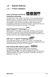
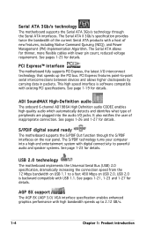
...!™ Technology The motherboard supports the AMD Cool ʻnʼ Quiet!™ Technology that dynamically and automatically changes the CPU speed, voltage and amount of power depending on AMDʼs 64-bit and 32-bit architecture, which represents the landmark introduction of system memory using DDR400/333/266 DIMMs. The ultra...) memory technology, the motherboard supports up to 48 times faster than other existing technologies. See page 1-9 for the latest 3D graphics, multimedia, and Internet applications. ASUS A8V-X 1-3
...!™ Technology The motherboard supports the AMD Cool ʻnʼ Quiet!™ Technology that dynamically and automatically changes the CPU speed, voltage and amount of power depending on AMDʼs 64-bit and 32-bit architecture, which represents the landmark introduction of system memory using DDR400/333/266 DIMMs. The ultra...) memory technology, the motherboard supports up to 48 times faster than other existing technologies. See page 1-9 for the latest 3D graphics, multimedia, and Internet applications. ASUS A8V-X 1-3
A8V-X User's Manual for English Edition
Page 16
... supports the S/PDIF Out function through the Serial ATA interfaces. The S/PDIF technology turns your computer into the audio I /O interconnect technology that speeds up to powerful audio and speaker systems. See page 1-23 for thinner, more flexible cables with high bandwidth speeds up the PCI bus. AGP 8X support The... carrying data in packets. See pages 1-25 for details. It also notifies the user of new features, including Native Command Queuing (NCQ), and Power Management (PM) Implementation Algorithm.
... supports the S/PDIF Out function through the Serial ATA interfaces. The S/PDIF technology turns your computer into the audio I /O interconnect technology that speeds up to powerful audio and speaker systems. See page 1-23 for thinner, more flexible cables with high bandwidth speeds up the PCI bus. AGP 8X support The... carrying data in packets. See pages 1-25 for details. It also notifies the user of new features, including Native Command Queuing (NCQ), and Power Management (PM) Implementation Algorithm.
A8V-X User's Manual for English Edition
Page 18
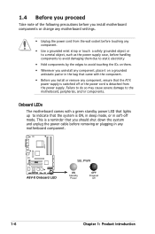
... so may cause severe damage to indicate that you should shut down the system and unplug the power cable before removing or plugging in soft-off mode. A8V-X ® A8V-X Onboard LED SB_PWR ON Standby Power OFF Powered Off 1-6 Chapter 1: Product introduction 1.4 Before you proceed Take note of the following precautions before you install motherboard...
... so may cause severe damage to indicate that you should shut down the system and unplug the power cable before removing or plugging in soft-off mode. A8V-X ® A8V-X Onboard LED SB_PWR ON Standby Power OFF Powered Off 1-6 Chapter 1: Product introduction 1.4 Before you proceed Take note of the following precautions before you install motherboard...
A8V-X User's Manual for English Edition
Page 19
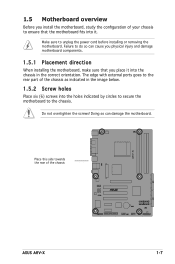
... into the chassis in the image below. 1.5.2 Screw holes Place six (6) screws into the holes indicated by circles to secure the motherboard to unplug the power cord before installing or removing the motherboard. Do not overtighten the screws! Make sure to the chassis. Doing so can cause you physical injury and... the motherboard, make sure that you install the motherboard, study the configuration of your chassis to the rear part of the chassis ® A8V-X ASUS A8V-X 1-7 Place this side towards the rear of the chassis as indicated in the correct orientation.
... into the chassis in the image below. 1.5.2 Screw holes Place six (6) screws into the holes indicated by circles to secure the motherboard to unplug the power cord before installing or removing the motherboard. Do not overtighten the screws! Make sure to the chassis. Doing so can cause you physical injury and... the motherboard, make sure that you install the motherboard, study the configuration of your chassis to the rear part of the chassis ® A8V-X ASUS A8V-X 1-7 Place this side towards the rear of the chassis as indicated in the correct orientation.

A8V-X User's Manual for English Edition
Page 20
Socket 939 A8V-X DDR DIMM_A1 (64 bit,184-pin module) DDR DIMM_A2 (64 bit,184-pin module) DDR DIMM_B1 (64 bit,184-pin module) DDR DIMM_B2 (64 bit,... AUX CD AD1986A SPDIF_OUT AGP PCI1 ® PCI2 PCI3 VIA VT8251 SATA4 SATA2 ITE IT8712F-A GAME PCIEX1_1 PCIEX1_2 4Mbit BIOS CR2032 3V Lithium Cell CMOS Power FLOPPY USB56 USBPW5678 CLRTC SATA3 SATA1 CHA_FAN SB_PWR USB78 CHASISS PANEL SEC_IDE 1-8 Chapter 1: Product introduction
Socket 939 A8V-X DDR DIMM_A1 (64 bit,184-pin module) DDR DIMM_A2 (64 bit,184-pin module) DDR DIMM_B1 (64 bit,184-pin module) DDR DIMM_B2 (64 bit,... AUX CD AD1986A SPDIF_OUT AGP PCI1 ® PCI2 PCI3 VIA VT8251 SATA4 SATA2 ITE IT8712F-A GAME PCIEX1_1 PCIEX1_2 4Mbit BIOS CR2032 3V Lithium Cell CMOS Power FLOPPY USB56 USBPW5678 CLRTC SATA3 SATA1 CHA_FAN SB_PWR USB78 CHASISS PANEL SEC_IDE 1-8 Chapter 1: Product introduction
A8V-X User's Manual for English Edition
Page 28
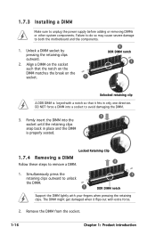
... DIMM lightly with extra force. 2. Firmly insert the DIMM into a socket to avoid damaging the DIMM. 3 3. Simultaneously press the retaining clips outward to unplug the power supply before adding or removing DIMMs or other system components.
... DIMM lightly with extra force. 2. Firmly insert the DIMM into a socket to avoid damaging the DIMM. 3 3. Simultaneously press the retaining clips outward to unplug the power supply before adding or removing DIMMs or other system components.

A8V-X User's Manual for English Edition
Page 29
The following sub-sections describe the slots and the expansion cards that you intend to use . 4. See Chapter 2 for the card. 2. ASUS A8V-X 1-17 Before installing the expansion card, read the documentation that came with the slot and press firmly until the card is already installed ... card. Remove the bracket opposite the slot that they support. Assign an IRQ to the tables on the slot. 5. We recommended to unplug the power cord before installing an AGP 8X card. 1.8.1 Installing an expansion card To install an expansion card: 1. Keep the screw for the expansion card. ...
The following sub-sections describe the slots and the expansion cards that you intend to use . 4. See Chapter 2 for the card. 2. ASUS A8V-X 1-17 Before installing the expansion card, read the documentation that came with the slot and press firmly until the card is already installed ... card. Remove the bracket opposite the slot that they support. Assign an IRQ to the tables on the slot. 5. We recommended to unplug the power cord before installing an AGP 8X card. 1.8.1 Installing an expansion card To install an expansion card: 1. Keep the screw for the expansion card. ...

A8V-X User's Manual for English Edition
Page 32
... (CPU Parameter Recall) feature. For system failure due to pins 2-3. Remove the onboard battery. 3. Removing the cap will cause system boot failure! A8V-X ® A8V-X Clear RTC RAM CLRTC 12 23 Normal (Default) Clear CMOS You do not need to clear the RTC when the system hangs due to pins...down the key during the boot process and enter BIOS setup to default values. 1-20 Chapter 1: Product introduction Turn OFF the computer and unplug the power cord. 2. Except when clearing the RTC RAM, never remove the cap on pins 2-3 for about 5~10 seconds, then move the cap back to...
... (CPU Parameter Recall) feature. For system failure due to pins 2-3. Remove the onboard battery. 3. Removing the cap will cause system boot failure! A8V-X ® A8V-X Clear RTC RAM CLRTC 12 23 Normal (Default) Clear CMOS You do not need to clear the RTC when the system hangs due to pins...down the key during the boot process and enter BIOS setup to default values. 1-20 Chapter 1: Product introduction Turn OFF the computer and unplug the power cord. 2. Except when clearing the RTC RAM, never remove the cap on pins 2-3 for about 5~10 seconds, then move the cap back to...

A8V-X User's Manual for English Edition
Page 33
... 23 +5V +5VSB (Default) ® A8V-X Keyboard Power Setting ASUS A8V-X 1-21 Set to +5VSB to wake up from S1 sleep mode (CPU stopped, DRAM refreshed, system running in the BIOS. Keyboard power (3-pin KBPWR) This jumper allows you press a key on the keyboard (the default is the Space Bar). This feature requires an ATX...
... 23 +5V +5VSB (Default) ® A8V-X Keyboard Power Setting ASUS A8V-X 1-21 Set to +5VSB to wake up from S1 sleep mode (CPU stopped, DRAM refreshed, system running in the BIOS. Keyboard power (3-pin KBPWR) This jumper allows you press a key on the keyboard (the default is the Space Bar). This feature requires an ATX...

A8V-X User's Manual for English Edition
Page 40
...W is inadequate. • You must install a PSU with more power-consuming devices. otherwise, the system will not boot up if the power is recommended for an ATX power supply plugs. ATX12V GND +12V DC GND +12V DC A8V-X ATXPWR +3.3VDC -12.0VDC ® COM PS_ON# COM COM COM... -5.0VDC A8V-X ATX Power Connectors +5.0VDC +5.0VDC +3.3VDC +3.3VDC COM +5.0VDC COM...
...W is inadequate. • You must install a PSU with more power-consuming devices. otherwise, the system will not boot up if the power is recommended for an ATX power supply plugs. ATX12V GND +12V DC GND +12V DC A8V-X ATXPWR +3.3VDC -12.0VDC ® COM PS_ON# COM COM COM... -5.0VDC A8V-X ATX Power Connectors +5.0VDC +5.0VDC +3.3VDC +3.3VDC COM +5.0VDC COM...

A8V-X User's Manual for English Edition
Page 42
... connector. Refer to the connector description below for details. • System power LED (Green 3-pin PLED) This 3-pin connector is for the system power LED. PLED SPEAKER PLED+ PLED+5V Ground Ground Speaker A8V-X PANEL IDE_LED+ IDE_LED- System panel connector (20-pin PANEL) This connector... supports several chassis-mounted functions. Pressing the power button turns the system ON or puts the ...
... connector. Refer to the connector description below for details. • System power LED (Green 3-pin PLED) This 3-pin connector is for the system power LED. PLED SPEAKER PLED+ PLED+5V Ground Ground Speaker A8V-X PANEL IDE_LED+ IDE_LED- System panel connector (20-pin PANEL) This connector... supports several chassis-mounted functions. Pressing the power button turns the system ON or puts the ...

A8V-X User's Manual for English Edition
Page 45
... Save the BIOS file to display the following. Floppy found !" Reading file "A8V-X.ROM". The EZ Flash utility is built-in the drive. Press + during the Power-On Self Tests (POST). EZFlash starting BIOS update Checking for floppy... error message appears ...64258;oppy... 4. When the correct BIOS file is your optical drive. Completed. A "A8V-X.ROM not found!" Start programming... Make sure that D: is found in the floppy disk. ASUS A8V-X 2-3 Copy the original or the latest motherboard BIOS file to the bootable fl...
... Save the BIOS file to display the following. Floppy found !" Reading file "A8V-X.ROM". The EZ Flash utility is built-in the drive. Press + during the Power-On Self Tests (POST). EZFlash starting BIOS update Checking for floppy... error message appears ...64258;oppy... 4. When the correct BIOS file is your optical drive. Completed. A "A8V-X.ROM not found!" Start programming... Make sure that D: is found in the floppy disk. ASUS A8V-X 2-3 Copy the original or the latest motherboard BIOS file to the bootable fl...

A8V-X User's Manual for English Edition
Page 47
.... Boot the system in DOS mode, then at the DOS prompt. 2. Version 1.19 Copyright (C) 2003 American Megatrends, Inc. done Please restart your computer ASUS A8V-X 2-5 Do not turn off power during flash BIOS Reading file ..... A:\>afudos /iA8V-X.ROM 4. Erasing flash ..... Write the BIOS filename on the bootable floppy...
.... Boot the system in DOS mode, then at the DOS prompt. 2. Version 1.19 Copyright (C) 2003 American Megatrends, Inc. done Please restart your computer ASUS A8V-X 2-5 Do not turn off power during flash BIOS Reading file ..... A:\>afudos /iA8V-X.ROM 4. Erasing flash ..... Write the BIOS filename on the bootable floppy...

A8V-X User's Manual for English Edition
Page 53
.... The Setup program is designed to use as easy to download the latest BIOS file for most conditions to "Run Setup". ASUS A8V-X 2-11 This section explains how to configure your system, or prompted to ensure optimum performance. Select the Load Default Settings item... under the Exit Menu. Press during the Power-On Self-Test (POST) to ensure system compatibility and stability. 2.2 BIOS setup program This motherboard supports a programmable firmware chip that...
.... The Setup program is designed to use as easy to download the latest BIOS file for most conditions to "Run Setup". ASUS A8V-X 2-11 This section explains how to configure your system, or prompted to ensure optimum performance. Select the Load Default Settings item... under the Exit Menu. Press during the Power-On Self-Test (POST) to ensure system compatibility and stability. 2.2 BIOS setup program This motherboard supports a programmable firmware chip that...

A8V-X User's Manual for English Edition
Page 54
... Exit For changing the basic system configuration For changing the advanced system settings For changing the advanced power management (APM) configuration For changing the system boot configuration For selecting the exit options and loading default settings To select an ...
... Exit For changing the basic system configuration For changing the advanced system settings For changing the advanced power management (APM) configuration For changing the system boot configuration For selecting the exit options and loading default settings To select an ...


