
Motherboard DIY Troubleshooting Guide
Page 39
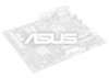
01 01 01 01 01 01 MODEM AUX (Black) CD (White) Left Audio Channel Ground Right Audio Channel Left Audio Channel Ground Right Audio Channel Modem-Out Ground Ground Modem-In A7V266-E A7V266-E Internal Audio Connectors A7V266-E MIC2 1 3 MIC Power MIC Input Ground A7V266-E Internal Microphone Connector 39
01 01 01 01 01 01 MODEM AUX (Black) CD (White) Left Audio Channel Ground Right Audio Channel Left Audio Channel Ground Right Audio Channel Modem-Out Ground Ground Modem-In A7V266-E A7V266-E Internal Audio Connectors A7V266-E MIC2 1 3 MIC Power MIC Input Ground A7V266-E Internal Microphone Connector 39

Motherboard DIY Troubleshooting Guide
Page 41
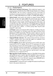
01 01 01 01 01 01 GND GND A7V266-E A7V266-E Digital Audio Interface SPDIFOUT SPDIFIN +5Volt (Power Supply Stand By) Chassis Signal Ground CHASSIS A7V266-E 1 A7V266-E Chassis Open Alarm Lead 41
01 01 01 01 01 01 GND GND A7V266-E A7V266-E Digital Audio Interface SPDIFOUT SPDIFIN +5Volt (Power Supply Stand By) Chassis Signal Ground CHASSIS A7V266-E 1 A7V266-E Chassis Open Alarm Lead 41

Motherboard DIY Troubleshooting Guide
Page 42
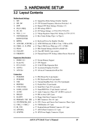
Keyboard Lock Speaker Power LED Connector PLED+ PLEDKeylock Ground +5V Ground Ground Speaker MLED+ MLEDExtSMI# Ground PWR GND Reset Ground A7V266-E Message LED SMI Lead A7V266-E System Panel Connectors Reset SW ATX Power Switch* 42 01 01 01 01 01 01 01 01 01 MIC2 AGND Line in_L AGND2 Line in_R AAPANEL A7V266-E A7V266-E Audio Panel Connectors MICPWR Line out_L AGND3 Line out_R A7V266-E A7V266-E Smartcard NC NC SCRREST NC SCRUI SCRRES# SMARTCARD 1 VCC NC SCRFET# SCRCLK NC GND NC2 * Requires an ATX power supply.
Keyboard Lock Speaker Power LED Connector PLED+ PLEDKeylock Ground +5V Ground Ground Speaker MLED+ MLEDExtSMI# Ground PWR GND Reset Ground A7V266-E Message LED SMI Lead A7V266-E System Panel Connectors Reset SW ATX Power Switch* 42 01 01 01 01 01 01 01 01 01 MIC2 AGND Line in_L AGND2 Line in_R AAPANEL A7V266-E A7V266-E Audio Panel Connectors MICPWR Line out_L AGND3 Line out_R A7V266-E A7V266-E Smartcard NC NC SCRREST NC SCRUI SCRRES# SMARTCARD 1 VCC NC SCRFET# SCRCLK NC GND NC2 * Requires an ATX power supply.

A7V266-E User Manual
Page 5
... 95 6.3 Multi-Channel Audio Feature Setup 100 6.4 ASUS Live Update 102 6.5 3Deep Color Tuner 103 6.6 CyberLink PowerPlayer SE 105 6.7 CyberLink VideoLive Mail 106 7. APPENDIX 109 7.1 Modem Riser 109 7.1.1 56K Software Modem 109 7.1.2 Primary/Seconday MR 109 7.1.3 Hardware Installation Procedure 109 7.1.4 Software Setup in Windows 98 110 7.2 Glossary 111 INDEX 115 ASUS A7V266-E User's Manual...
... 95 6.3 Multi-Channel Audio Feature Setup 100 6.4 ASUS Live Update 102 6.5 3Deep Color Tuner 103 6.6 CyberLink PowerPlayer SE 105 6.7 CyberLink VideoLive Mail 106 7. APPENDIX 109 7.1 Modem Riser 109 7.1.1 56K Software Modem 109 7.1.2 Primary/Seconday MR 109 7.1.3 Hardware Installation Procedure 109 7.1.4 Software Setup in Windows 98 110 7.2 Glossary 111 INDEX 115 ASUS A7V266-E User's Manual...

A7V266-E User Manual
Page 9
ASUS A7V266-E User's Manual 9 The slot is keyed to four Ultra DMA/100/66, PIO Modes 3 &...Floppy disk connector: Supports the floppy disk drive. • Wake-On-LAN: Supports Wake-On-LAN activity through an optional ASUS PCI-L101 10 /100 Fast Ethernet PCI card. • Wake-On-Ring: Supports Wake-On-Ring activity through a ...5VSB). FEATURES Specifications 2. This connector supports a joystick or a game pad for playing games, and MIDI devices for playing or editing audio files. • Parallel port: 25-pin port connects a parallel printer or other devices. • PS/2 mouse port: Green 6-...
ASUS A7V266-E User's Manual 9 The slot is keyed to four Ultra DMA/100/66, PIO Modes 3 &...Floppy disk connector: Supports the floppy disk drive. • Wake-On-LAN: Supports Wake-On-LAN activity through an optional ASUS PCI-L101 10 /100 Fast Ethernet PCI card. • Wake-On-Ring: Supports Wake-On-Ring activity through a ...5VSB). FEATURES Specifications 2. This connector supports a joystick or a game pad for playing games, and MIDI devices for playing or editing audio files. • Parallel port: 25-pin port connects a parallel printer or other devices. • PS/2 mouse port: Green 6-...
A7V266-E User Manual
Page 10
...80-conductor cable). • Concurrent PCI: Concurrent PCI allows multiple PCI transfers from PCI master busses to the memory and processor. 10 ASUS A7V266-E User's Manual The chip supports software access to 2.1 GB/s for 133MHz DDR SDRAM and 1.6GB/s for UltraDMA/100 through the ...memory technology increases performance by PC'99. • High-Speed Data Transfer Interface: Support for 100MHz DDR SDRAM. • Onboard Audio: Audio models come with energy saving standards. UltraDMA/100 is backward compatible with additional support for Windows95/98/NT . With these features employed...
...80-conductor cable). • Concurrent PCI: Concurrent PCI allows multiple PCI transfers from PCI master busses to the memory and processor. 10 ASUS A7V266-E User's Manual The chip supports software access to 2.1 GB/s for 133MHz DDR SDRAM and 1.6GB/s for UltraDMA/100 through the ...memory technology increases performance by PC'99. • High-Speed Data Transfer Interface: Support for 100MHz DDR SDRAM. • Onboard Audio: Audio models come with energy saving standards. UltraDMA/100 is backward compatible with additional support for Windows95/98/NT . With these features employed...

A7V266-E User Manual
Page 12
...Voltage Monitoring (integrated in ASUS ASIC) ......... 9 Special Feature Audio Features Onboard LED 21 (on audio models only) CMI8738 6-Channel Audio Controller Chipset 15 1 ASUS iPanel Audio Connector 16 1 Game/MIDI... Port Top) 23 1 Line Out Connector Bottom, left) 23 1 Line In Connector Bottom, center) 23 1 Microphone Connector Bottom, right) 23 Internal Audio Connectors Power ATX Power Supply Connector 5 Form Factor ATX 12 ASUS A7V266...
...Voltage Monitoring (integrated in ASUS ASIC) ......... 9 Special Feature Audio Features Onboard LED 21 (on audio models only) CMI8738 6-Channel Audio Controller Chipset 15 1 ASUS iPanel Audio Connector 16 1 Game/MIDI... Port Top) 23 1 Line Out Connector Bottom, left) 23 1 Line In Connector Bottom, center) 23 1 Microphone Connector Bottom, right) 23 Internal Audio Connectors Power ATX Power Supply Connector 5 Form Factor ATX 12 ASUS A7V266...

A7V266-E User Manual
Page 14
... Audio Controller Accelerated Graphics Port (AGP Pro) PCI 1 DSW SYSCLK PROMISE IDE Controller PCI 2 SMARTCARD PCI 3 CD PCI 4 PCI 5 ACR A7V266-E VIA VT8233 Chipset CR2032 3V Lithium Cell CMOS Power ACRUSB SMB_CON JTPWR CLR_RTC ASUS FLOPPY ASIC with Hardware JEN Monitor CHA_FAN CHASSIS CHA IR_CON USB45_PWR IDELED USB23_PWR USB2_3 USB4_5 AFPANEL PANEL 14 ASUS A7V266...
... Audio Controller Accelerated Graphics Port (AGP Pro) PCI 1 DSW SYSCLK PROMISE IDE Controller PCI 2 SMARTCARD PCI 3 CD PCI 4 PCI 5 ACR A7V266-E VIA VT8233 Chipset CR2032 3V Lithium Cell CMOS Power ACRUSB SMB_CON JTPWR CLR_RTC ASUS FLOPPY ASIC with Hardware JEN Monitor CHA_FAN CHASSIS CHA IR_CON USB45_PWR IDELED USB23_PWR USB2_3 USB4_5 AFPANEL PANEL 14 ASUS A7V266...
A7V266-E User Manual
Page 15
...pin) 13) IR_CON p. 37 Standard Infrared Module Connector (10-1 pin) 14) AFPANEL p. 37 ASUS iPanel Connector (12-1 pin) 15) ATXPWR p. 38 ATX Power Supply Connector (20 pin) ASUS A7V266-E User's Manual 15 HARDWARE SETUP 3.2 Layout Contents Motherboard Settings 1) JEN p. 18 JumperFree Mode ... COM1/COM2 p. 32 Serial Ports (9 pin /10-1 pin male) 6) GAME_AUDIO p. 33 Game/MIDI Port (15-pin female) (optional) 7) AUDIO p. 33 Audio Connectors (Three 1/8" AUDIO) (optional) 8) IDELED p. 34 IDE Activity LED (2 pin) 9) FLOPPY p. 34 Floppy Disk Drive Connector (34 pin) 10) PRIMARY / SEC....
...pin) 13) IR_CON p. 37 Standard Infrared Module Connector (10-1 pin) 14) AFPANEL p. 37 ASUS iPanel Connector (12-1 pin) 15) ATXPWR p. 38 ATX Power Supply Connector (20 pin) ASUS A7V266-E User's Manual 15 HARDWARE SETUP 3.2 Layout Contents Motherboard Settings 1) JEN p. 18 JumperFree Mode ... COM1/COM2 p. 32 Serial Ports (9 pin /10-1 pin male) 6) GAME_AUDIO p. 33 Game/MIDI Port (15-pin female) (optional) 7) AUDIO p. 33 Audio Connectors (Three 1/8" AUDIO) (optional) 8) IDELED p. 34 IDE Activity LED (2 pin) 9) FLOPPY p. 34 Floppy Disk Drive Connector (34 pin) 10) PRIMARY / SEC....

A7V266-E User Manual
Page 16
H/W SETUP Layout Contents 16 ASUS A7V266-E User's Manual HARDWARE SETUP 16) SMB p. 38 SMBus Connector (5-1 pin) 17) CD/AUX/MODEM p. 39 Internal Audio Connectors (Three 4-1 pin) (optional) 18) MIC2 p. 39 Internal Microphone Connector (3 pin) (optional) 19) HPHONE p. 40... Power Supply Thermal Sensor (2 pin) 21) SPDIFOUT / CDSPDIFIN p. 41 Digital audio Interfaces (2 pin) (optional) 22) CHASSIS p. 41 Chassis Intrusion Lead (2 pin) 23) AAPANEL p. 42 ASUS iPanel Audio Connector (10-1 pin) 24) SMARTCON p. 42 ASUS SmartCard Connector (14-1 pin) 25) PWR.LED (PANEL) p. 43 System Power...
H/W SETUP Layout Contents 16 ASUS A7V266-E User's Manual HARDWARE SETUP 16) SMB p. 38 SMBus Connector (5-1 pin) 17) CD/AUX/MODEM p. 39 Internal Audio Connectors (Three 4-1 pin) (optional) 18) MIC2 p. 39 Internal Microphone Connector (3 pin) (optional) 19) HPHONE p. 40... Power Supply Thermal Sensor (2 pin) 21) SPDIFOUT / CDSPDIFIN p. 41 Digital audio Interfaces (2 pin) (optional) 22) CHASSIS p. 41 Chassis Intrusion Lead (2 pin) 23) AAPANEL p. 42 ASUS iPanel Audio Connector (10-1 pin) 24) SMARTCON p. 42 ASUS SmartCard Connector (14-1 pin) 25) PWR.LED (PANEL) p. 43 System Power...
A7V266-E User Manual
Page 21
...sockets. It is generated according to use CPU Default as the CPU core voltage. A7V266-E A7V266-E Bass Center Setting BCS 12 23 type 1 Bass (CENTER/BASS) (Default) type 2 Bass (BASS/CENTER) ASUS A7V266-E User's Manual 21 3. A7V266-E 123 VID4 VID3 VID2 VID1 CPU Default 123 VID4 VID3 VID2 VID1 1.85/1.... allow you to adjust output for 4 or 6 speaker audio. Make sure a test is made using the C-Media Audio Driver software setup available on the CPU used. No audio standard exists for the three pick-up surfaces on male audio jacks, therefore it may be necessary to switch jumpers from...
...sockets. It is generated according to use CPU Default as the CPU core voltage. A7V266-E A7V266-E Bass Center Setting BCS 12 23 type 1 Bass (CENTER/BASS) (Default) type 2 Bass (BASS/CENTER) ASUS A7V266-E User's Manual 21 3. A7V266-E 123 VID4 VID3 VID2 VID1 CPU Default 123 VID4 VID3 VID2 VID1 1.85/1.... allow you to adjust output for 4 or 6 speaker audio. Make sure a test is made using the C-Media Audio Driver software setup available on the CPU used. No audio standard exists for the three pick-up surfaces on male audio jacks, therefore it may be necessary to switch jumpers from...

A7V266-E User Manual
Page 22
... 01 01 01 01 3. Setting Enable Disable KBWK [1-2] (default) [2-3] KBWK A7V266-E 12 Enable (Default) 23 Disable A7V266-E Keyboard Wake Up 9) ACR/USB Selection (ACRUSB1, ACRUSB2) (audio models only) When set to pins 1-2, these jumpers.) IMPORTANT! Setting the jumpers... to activate USB port 3. The default setting for both jumpers accordingly when selecting a device. 3. Set this to power up function. This feature requires an ATX power supply that can supply at least 300mA on ACR 22 ASUS A7V266...
... 01 01 01 01 3. Setting Enable Disable KBWK [1-2] (default) [2-3] KBWK A7V266-E 12 Enable (Default) 23 Disable A7V266-E Keyboard Wake Up 9) ACR/USB Selection (ACRUSB1, ACRUSB2) (audio models only) When set to pins 1-2, these jumpers.) IMPORTANT! Setting the jumpers... to activate USB port 3. The default setting for both jumpers accordingly when selecting a device. 3. Set this to power up function. This feature requires an ATX power supply that can supply at least 300mA on ACR 22 ASUS A7V266...

A7V266-E User Manual
Page 29
...PCI slot 2 PCI slot 3 PCI slot 4 PCI slot 5 AGPPro slot ACR slot Onboard audio controller Onboard USB controller Onboard IDE controller INT-A - shared shared - - - shared - - used . shared shared ASUS A7V266-E User's Manual 29 3. In a standard design, there are 16 IRQs available but most of... them are usually available for this table when configuring your system and for expansion cards. If your motherboard has PCI audio onboard, an additional IRQ will make...
...PCI slot 2 PCI slot 3 PCI slot 4 PCI slot 5 AGPPro slot ACR slot Onboard audio controller Onboard USB controller Onboard IDE controller INT-A - shared shared - - - shared - - used . shared shared ASUS A7V266-E User's Manual 29 3. In a standard design, there are 16 IRQs available but most of... them are usually available for this table when configuring your system and for expansion cards. If your motherboard has PCI audio onboard, an additional IRQ will make...

A7V266-E User Manual
Page 30
... TOP VIEW 28-pin bay Rib CAUTION! H/W SETUP Expansion Cards A7V266-E A7V266-E Advanced Communication Riser (ACR) 30 ASUS A7V266-E User's Manual The ACR slot on the motherboard shares the same expansion slot with the Audio Modem Riser (AMR) cards. The ACR slot is shipped with ...tab 3.7.4 Advanced Communication Riser (ACR) Slot This motherboard has an Advanced Communication Riser (ACR) slot for communications and audio subsystems. The slot supports modem, audio, LAN, and Home Phoneline Networking Alliance (HPNA) or Home Networking cards. The AGP Pro slot is backward compatible ...
... TOP VIEW 28-pin bay Rib CAUTION! H/W SETUP Expansion Cards A7V266-E A7V266-E Advanced Communication Riser (ACR) 30 ASUS A7V266-E User's Manual The ACR slot on the motherboard shares the same expansion slot with the Audio Modem Riser (AMR) cards. The ACR slot is shipped with ...tab 3.7.4 Advanced Communication Riser (ACR) Slot This motherboard has an Advanced Communication Riser (ACR) slot for communications and audio subsystems. The slot supports modem, audio, LAN, and Home Phoneline Networking Alliance (HPNA) or Home Networking cards. The AGP Pro slot is backward compatible ...

A7V266-E User Manual
Page 33
... Mic (pink) connects a microphone. 3. The Line In (light blue) connects a tape players or other audio sources. NOTE: The functions of the audio connectors Line Out, Line In, and Mic change when the 6-channel audio feature is enabled. H/W SETUP Connectors ASUS A7V266-E User's Manual 33 HARDWARE SETUP 6) Game/MIDI Ports (Gold 15-pin GAME_AUDIO) (optional) This...
... Mic (pink) connects a microphone. 3. The Line In (light blue) connects a tape players or other audio sources. NOTE: The functions of the audio connectors Line Out, Line In, and Mic change when the 6-channel audio feature is enabled. H/W SETUP Connectors ASUS A7V266-E User's Manual 33 HARDWARE SETUP 6) Game/MIDI Ports (Gold 15-pin GAME_AUDIO) (optional) This...

A7V266-E User Manual
Page 39
...) (optional) This connector allows you to the ATX connector. You may only use one microphone at a time. A7V266-E MIC2 1 3 MIC Power MIC Input Ground A7V266-E Internal Microphone Connector ASUS A7V266-E User's Manual 39 HARDWARE SETUP 17) Internal Audio Connectors (4-1 pin CD, AUX, MODEM) (optional) These connectors allow you to connect chassis-mounted microphone to the...
...) (optional) This connector allows you to the ATX connector. You may only use one microphone at a time. A7V266-E MIC2 1 3 MIC Power MIC Input Ground A7V266-E Internal Microphone Connector ASUS A7V266-E User's Manual 39 HARDWARE SETUP 17) Internal Audio Connectors (4-1 pin CD, AUX, MODEM) (optional) These connectors allow you to connect chassis-mounted microphone to the...

A7V266-E User Manual
Page 41
... SETUP Connectors 01 01 01 01 01 01 3. 3. HARDWARE SETUP 21) Digital Audio Interfaces (2-pin SPDIFOUT/CDSPDIFIN) (optional) These connectors connect SPDIF audio cable that allows digital instead of analog sound output from CD-ROM, DVD-ROM, ...A7V266-E A7V266-E Digital Audio Interface SPDIFOUT SPDIFIN 22) Chassis Open Alarm Lead (4-pin CHASSIS) This lead is then be processed by software such as LDCM. This requires an external detection mechanism such as SoundBlaster. CHASSIS A7V266-E 1 A7V266-E Chassis Open Alarm Lead +5Volt (Power Supply Stand By) Chassis Signal Ground ASUS A7V266...
... SETUP Connectors 01 01 01 01 01 01 3. 3. HARDWARE SETUP 21) Digital Audio Interfaces (2-pin SPDIFOUT/CDSPDIFIN) (optional) These connectors connect SPDIF audio cable that allows digital instead of analog sound output from CD-ROM, DVD-ROM, ...A7V266-E A7V266-E Digital Audio Interface SPDIFOUT SPDIFIN 22) Chassis Open Alarm Lead (4-pin CHASSIS) This lead is then be processed by software such as LDCM. This requires an external detection mechanism such as SoundBlaster. CHASSIS A7V266-E 1 A7V266-E Chassis Open Alarm Lead +5Volt (Power Supply Stand By) Chassis Signal Ground ASUS A7V266...

A7V266-E User Manual
Page 42
...) Connect the audio cable from the memory chip of PC/SC smart cards. H/W SETUP Connectors 3. AAPANEL A7V266-E A7V266-E Audio Panel Connectors 24) ASUS SmartCard Connector (14-1 pin SMARTCON) This connector attaches to this for front panel audio control. SMARTCARD A7V266-E 1 A7V266-E Smartcard NC NC SCRREST NC SCRUI SCRRES# VCC NC SCRFET# SCRCLK NC GND NC2 42 ASUS A7V266-E User's Manual...
...) Connect the audio cable from the memory chip of PC/SC smart cards. H/W SETUP Connectors 3. AAPANEL A7V266-E A7V266-E Audio Panel Connectors 24) ASUS SmartCard Connector (14-1 pin SMARTCON) This connector attaches to this for front panel audio control. SMARTCARD A7V266-E 1 A7V266-E Smartcard NC NC SCRREST NC SCRUI SCRRES# VCC NC SCRFET# SCRCLK NC GND NC2 42 ASUS A7V266-E User's Manual...

A7V266-E User Manual
Page 64
... does not support this feature, otherwise the system may not boot. Configuration options: [Disabled] [Enabled] 4. BIOS SETUP Chip Configuration 64 ASUS A7V266-E User's Manual BIOS SETUP AGP Drive Strength [Auto] Configuration options: [Auto] [Manual] Graphics Aperture Size [32MB] This feature allows ... memory up to other system components. Configuration options: [Enabled] [Auto Detect] [Disabled] Onboard PCI Audio Enable [Enabled] This field enables PCI audio. Setting the address space to a particular setting makes that memory space unavailable to 16MB. Expansion cards can...
... does not support this feature, otherwise the system may not boot. Configuration options: [Disabled] [Enabled] 4. BIOS SETUP Chip Configuration 64 ASUS A7V266-E User's Manual BIOS SETUP AGP Drive Strength [Auto] Configuration options: [Auto] [Manual] Graphics Aperture Size [32MB] This feature allows ... memory up to other system components. Configuration options: [Enabled] [Auto Detect] [Disabled] Onboard PCI Audio Enable [Enabled] This field enables PCI audio. Setting the address space to a particular setting makes that memory space unavailable to 16MB. Expansion cards can...

A7V266-E User Manual
Page 66
... port. [Normal] allows normal-speed operation but in a two-way mode. Configuration options: [Disabled] [Auto] 66 ASUS A7V266-E User's Manual 4. If there are using any modem/audio device. BIOS SETUP Parallel Port Mode [ECP+EPP] This field allows you to operate in bidirectional DMA mode; [ECP+EPP... DMA Select [3] This field allows you to set the appropriate field to select the I /O Device Config Onboard AC97 Modem Controller [Auto] Onboard AC97 Audio Controller [Auto] [Auto] allows the BIOS to detect whether you select [ECP] or [ECP+EPP] in Parallel Port Mode above. BIOS SETUP I...
... port. [Normal] allows normal-speed operation but in a two-way mode. Configuration options: [Disabled] [Auto] 66 ASUS A7V266-E User's Manual 4. If there are using any modem/audio device. BIOS SETUP Parallel Port Mode [ECP+EPP] This field allows you to operate in bidirectional DMA mode; [ECP+EPP... DMA Select [3] This field allows you to set the appropriate field to select the I /O Device Config Onboard AC97 Modem Controller [Auto] Onboard AC97 Audio Controller [Auto] [Auto] allows the BIOS to detect whether you select [ECP] or [ECP+EPP] in Parallel Port Mode above. BIOS SETUP I...

