A7V266-E User Manual
Page 2
... ARISING FROM ANY DEFECT OR ERROR IN THIS MANUAL OR PRODUCT. For previous or updated manuals, BIOS, drivers, or product release information, contact ASUS at http://www.asus.com.tw or through any means, except documentation kept by the third digit in the manual revision...ASUS"). USER'S NOTICE No part of this manual may or may be reproduced, transmitted, transcribed, stored in a retrieval system, or translated into any language in any form or by any of the product is defaced or missing. Product Name: ASUS A7V266-E Manual Revision: 1.00 E883 Release Date: October 2001 2 ASUS A7V266...
... ARISING FROM ANY DEFECT OR ERROR IN THIS MANUAL OR PRODUCT. For previous or updated manuals, BIOS, drivers, or product release information, contact ASUS at http://www.asus.com.tw or through any means, except documentation kept by the third digit in the manual revision...ASUS"). USER'S NOTICE No part of this manual may or may be reproduced, transmitted, transcribed, stored in a retrieval system, or translated into any language in any form or by any of the product is defaced or missing. Product Name: ASUS A7V266-E Manual Revision: 1.00 E883 Release Date: October 2001 2 ASUS A7V266...
A7V266-E User Manual
Page 4
... 30 3.8 Connectors 31 3.8.1 External Connectors 31 3.9 Starting Up the First Time 44 4. BIOS SETUP 45 4.1 Managing and Updating Your BIOS 45 4.1.1 Upon First Use of the Computer System 45 4.1.2 Updating BIOS Procedures 47 4.2 BIOS Setup Program 49 4.2.1 BIOS Menu Bar 50 4.2.2 Legend Bar 50 4 ASUS A7V266-E User's Manual INTRODUCTION 7 1.1 How This Manual Is Organized 7 1.2 Item Checklist 7 2. CONTENTS...
... 30 3.8 Connectors 31 3.8.1 External Connectors 31 3.9 Starting Up the First Time 44 4. BIOS SETUP 45 4.1 Managing and Updating Your BIOS 45 4.1.1 Upon First Use of the Computer System 45 4.1.2 Updating BIOS Procedures 47 4.2 BIOS Setup Program 49 4.2.1 BIOS Menu Bar 50 4.2.2 Legend Bar 50 4 ASUS A7V266-E User's Manual INTRODUCTION 7 1.1 How This Manual Is Organized 7 1.2 Item Checklist 7 2. CONTENTS...

A7V266-E User Manual
Page 7
... divided into the following sections: 1. Instructions on setting up the BIOS Instructions on setting up the included software Reference material for two 3.5" floppy disk drives (1) ASUS Support CD with drivers and utilities (1) Bag of spare jumper caps (1) ASUS 2-port USB Connector Set (1) User's Manual ASUS A7V266-E User's Manual 7 INTRODUCTION 1.1 How This Manual Is Organized This...
... divided into the following sections: 1. Instructions on setting up the BIOS Instructions on setting up the included software Reference material for two 3.5" floppy disk drives (1) ASUS Support CD with drivers and utilities (1) Bag of spare jumper caps (1) ASUS 2-port USB Connector Set (1) User's Manual ASUS A7V266-E User's Manual 7 INTRODUCTION 1.1 How This Manual Is Organized This...

A7V266-E User Manual
Page 8
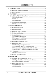
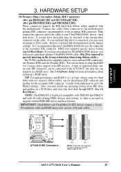
...from COM2 to use DIP switches come with the motherboard board to allow manual adjustment of up to each other. 8 ASUS A7V266-E User's Manual Data "striping," or RAID 0, improves speed performance as the protocol optimizes two identical hard disks to ...BIOS. Data "mirroring," or RAID 1, improves system fault tolerance as I /O controller also supports a floppy disk drive, PS/2 keyboard, and PS/2 mouse. • Promise® chip: The Promise IDE controller chip supports the ATA-100 protocol and Ultra DMA/100 data transfer speeds. FEATURES 2.1 ASUS A7V266-E Motherboard The ASUS A7V266...
...from COM2 to use DIP switches come with the motherboard board to allow manual adjustment of up to each other. 8 ASUS A7V266-E User's Manual Data "striping," or RAID 0, improves speed performance as the protocol optimizes two identical hard disks to ...BIOS. Data "mirroring," or RAID 1, improves system fault tolerance as I /O controller also supports a floppy disk drive, PS/2 keyboard, and PS/2 mouse. • Promise® chip: The Promise IDE controller chip supports the ATA-100 protocol and Ultra DMA/100 data transfer speeds. FEATURES 2.1 ASUS A7V266-E Motherboard The ASUS A7V266...

A7V266-E User Manual
Page 9
2. The slot is okay. • ATX power connector. ASUS A7V266-E User's Manual 9 FEATURES • Smart BIOS: 2Mb firmware enables Vcore and CPU/DDR SDRAM frequency adjustments, boot block write protection, and HD/SCSI/MO/ZIP/CD/Floppy boot selection. 2.1.2 Connections •...latest 1.5 volt AGP cards. • Floppy disk connector: Supports the floppy disk drive. • Wake-On-LAN: Supports Wake-On-LAN activity through an optional ASUS PCI-L101 10 /100 Fast Ethernet PCI card. • Wake-On-Ring: Supports Wake-On-Ring activity through a PCI modem card. • Smartcard Reader Connector...
2. The slot is okay. • ATX power connector. ASUS A7V266-E User's Manual 9 FEATURES • Smart BIOS: 2Mb firmware enables Vcore and CPU/DDR SDRAM frequency adjustments, boot block write protection, and HD/SCSI/MO/ZIP/CD/Floppy boot selection. 2.1.2 Connections •...latest 1.5 volt AGP cards. • Floppy disk connector: Supports the floppy disk drive. • Wake-On-LAN: Supports Wake-On-LAN activity through an optional ASUS PCI-L101 10 /100 Fast Ethernet PCI card. • Wake-On-Ring: Supports Wake-On-Ring activity through a PCI modem card. • Smartcard Reader Connector...
A7V266-E User Manual
Page 10
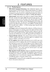
...audio controller that support OS Direct Power Management (OSPM) functionality. The chip supports software access to the memory and processor. 10 ASUS A7V266-E User's Manual A software package helps setup the multichannel PC sound system. • ACPI Ready: Advanced Configuration Power Interface (ACPI...Energy Saving Features for a multitude of new financial, telephonic, and mobile access services. • PC'99 Compliant: Both the BIOS and hardware levels of PS/SC compatible Smart Card security plus support for operating systems that supplies HRTF 3D positional audio functions....
...audio controller that support OS Direct Power Management (OSPM) functionality. The chip supports software access to the memory and processor. 10 ASUS A7V266-E User's Manual A software package helps setup the multichannel PC sound system. • ACPI Ready: Advanced Configuration Power Interface (ACPI...Energy Saving Features for a multitude of new financial, telephonic, and mobile access services. • PC'99 Compliant: Both the BIOS and hardware levels of PS/SC compatible Smart Card security plus support for operating systems that supplies HRTF 3D positional audio functions....

A7V266-E User Manual
Page 11
...ACPI OS support): The power LED indicates the system status. • Remote Ring-On (requires modem): This allows a computer to critical motherboard components. ASUS A7V266-E User's Manual 11 FEATURES 2.1.3 Intelligence • Auto Fan Off: The system fans powers off mode, depending on -hand, users can be turned...4 seconds when the system is in 4.5 Power Menu). With this benefit on the BIOS or OS setting (See PWR Button < 4 Secs in the working state places the system into one of the BIOS setting. • Fan Status Monitoring and Alarm: To prevent system overheat and system ...
...ACPI OS support): The power LED indicates the system status. • Remote Ring-On (requires modem): This allows a computer to critical motherboard components. ASUS A7V266-E User's Manual 11 FEATURES 2.1.3 Intelligence • Auto Fan Off: The system fans powers off mode, depending on -hand, users can be turned...4 seconds when the system is in 4.5 Power Menu). With this benefit on the BIOS or OS setting (See PWR Button < 4 Secs in the working state places the system into one of the BIOS setting. • Fan Status Monitoring and Alarm: To prevent system overheat and system ...

A7V266-E User Manual
Page 14
...Line Out VIA Line CPU_FAN KT266A In PWR_FAN Chipset Mic In 0 1 23 45 RAID / IDE JP1 JP2 LED Super I/O 2Mb BIOS AUX HPHOME MIC2 AAPANEL BCS MODEM SPDIF OUT CDSPDIF IN C-Media CMI8738 6CH Audio Controller Accelerated Graphics Port (AGP Pro) PCI 1 ...SMARTCARD PCI 3 CD PCI 4 PCI 5 ACR A7V266-E VIA VT8233 Chipset CR2032 3V Lithium Cell CMOS Power ACRUSB SMB_CON JTPWR CLR_RTC ASUS FLOPPY ASIC with Hardware JEN Monitor CHA_FAN CHASSIS CHA IR_CON USB45_PWR IDELED USB23_PWR USB2_3 USB4_5 AFPANEL PANEL 14 ASUS A7V266-E User's Manual H/W SETUP Motherboard Layout 3. ...
...Line Out VIA Line CPU_FAN KT266A In PWR_FAN Chipset Mic In 0 1 23 45 RAID / IDE JP1 JP2 LED Super I/O 2Mb BIOS AUX HPHOME MIC2 AAPANEL BCS MODEM SPDIF OUT CDSPDIF IN C-Media CMI8738 6CH Audio Controller Accelerated Graphics Port (AGP Pro) PCI 1 ...SMARTCARD PCI 3 CD PCI 4 PCI 5 ACR A7V266-E VIA VT8233 Chipset CR2032 3V Lithium Cell CMOS Power ACRUSB SMB_CON JTPWR CLR_RTC ASUS FLOPPY ASIC with Hardware JEN Monitor CHA_FAN CHASSIS CHA IR_CON USB45_PWR IDELED USB23_PWR USB2_3 USB4_5 AFPANEL PANEL 14 ASUS A7V266-E User's Manual H/W SETUP Motherboard Layout 3. ...

A7V266-E User Manual
Page 17
Install Expansion Cards 5. Configure the BIOS parameter settings 3.4 Motherboard Settings This section tells you work on them due to touch the IC chips on your computer: 1. Computer motherboards and .... HARDWARE SETUP 3.3 Hardware Setup Procedure Complete the following steps before handling computer components. 3. H/W SETUP Motherboard Settings 01 01 01 A7V266-E A7V266-E Onboard LED LED ON Standby Power OFF Powered Off ASUS A7V266-E User's Manual 17 WARNING! Whenever you install or remove any component, place the components on the internal components. 2. Install memory...
Install Expansion Cards 5. Configure the BIOS parameter settings 3.4 Motherboard Settings This section tells you work on them due to touch the IC chips on your computer: 1. Computer motherboards and .... HARDWARE SETUP 3.3 Hardware Setup Procedure Complete the following steps before handling computer components. 3. H/W SETUP Motherboard Settings 01 01 01 A7V266-E A7V266-E Onboard LED LED ON Standby Power OFF Powered Off ASUS A7V266-E User's Manual 17 WARNING! Whenever you install or remove any component, place the components on the internal components. 2. Install memory...

A7V266-E User Manual
Page 18
...The motherboard frequency is adjusted through the BIOS setup (see 4.4 Advanced Menu). The JumperFree™ mode allows processor settings to enable or disable the JumperFree™ mode. The illustration below shows all DIP switches (DIP_SW) to OFF. 18 ASUS A7V266-E User's Manual Setting JEN Enable (...JumperFree) [2-3] (default) Disable (Jumper Mode) [1-2] A7V266-E JEN CPU_RATIO ON 12345 SYSCLK ON 1234 12 23 ON OFF ON OFF Jumper Mode...
...The motherboard frequency is adjusted through the BIOS setup (see 4.4 Advanced Menu). The JumperFree™ mode allows processor settings to enable or disable the JumperFree™ mode. The illustration below shows all DIP switches (DIP_SW) to OFF. 18 ASUS A7V266-E User's Manual Setting JEN Enable (...JumperFree) [2-3] (default) Disable (Jumper Mode) [1-2] A7V266-E JEN CPU_RATIO ON 12345 SYSCLK ON 1234 12 23 ON OFF ON OFF Jumper Mode...

A7V266-E User Manual
Page 19
... 133.33MHz 140MHz AGP 60.67MHz 66.67MHz 70MHz (JumperFree Mode) PCI 33.33MHz 33.33MHz 35MHz A7V266-E CPU External Frequency Selection WARNING! Overclocking the processor is enabled, use BIOS setup in place of these switches. (Set Operating Frequency Setting to User Define under 4.4 Advanced Menu... to be set the CPU Frequency.) CPU_RATIO A7V266-E ON ON ON ON 12345 CPU_RATIO 8X ON 12345 8.5X ON 12345 9X ON 12345 9.5X 12345 CPU_RATIO 10X 12345 12345 10.5X (JumperFree Mode) A7V266-E CPU External Clock (BUS) Frequency Selection ASUS A7V266-E User's Manual 19 It may result in...
... 133.33MHz 140MHz AGP 60.67MHz 66.67MHz 70MHz (JumperFree Mode) PCI 33.33MHz 33.33MHz 35MHz A7V266-E CPU External Frequency Selection WARNING! Overclocking the processor is enabled, use BIOS setup in place of these switches. (Set Operating Frequency Setting to User Define under 4.4 Advanced Menu... to be set the CPU Frequency.) CPU_RATIO A7V266-E ON ON ON ON 12345 CPU_RATIO 8X ON 12345 8.5X ON 12345 9X ON 12345 9.5X 12345 CPU_RATIO 10X 12345 12345 10.5X (JumperFree Mode) A7V266-E CPU External Clock (BUS) Frequency Selection ASUS A7V266-E User's Manual 19 It may result in...
A7V266-E User Manual
Page 24
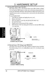
...BIOS setup to clear the Real Time Clock (RTC) RAM in CMOS, that include system setup information such as system passwords, is for Athlon/Duron and, [2-3], is powered by the onboard button cell battery. A7V266-E THEMCPU 12 23 ATHLON/DURON (Default) RESERVED A7V266-E THEMCPU Setting 24 ASUS A7V266... its thermal sensory capability. Remove the battery. 3. Plug the power cord and turn ON the computer. 6. H/W SETUP Motherboard Settings A7V266-E A7V266-E Clear RTC RAM CR2032 3V Lithium Cell CMOS Power CLRTC Remove and then replace the jumper cap. 13) Thermal Sensor CPU Setting ...
...BIOS setup to clear the Real Time Clock (RTC) RAM in CMOS, that include system setup information such as system passwords, is for Athlon/Duron and, [2-3], is powered by the onboard button cell battery. A7V266-E THEMCPU 12 23 ATHLON/DURON (Default) RESERVED A7V266-E THEMCPU Setting 24 ASUS A7V266... its thermal sensory capability. Remove the battery. 3. Plug the power cord and turn ON the computer. 6. H/W SETUP Motherboard Settings A7V266-E A7V266-E Clear RTC RAM CR2032 3V Lithium Cell CMOS Power CLRTC Remove and then replace the jumper cap. 13) Thermal Sensor CPU Setting ...

A7V266-E User Manual
Page 26
... support SPD (Serial Presence Detect) DIMMs. This is the memory of center. 01 01 01 A7V266-E A7V266-E 184-Pin DDR DIMM Sockets 104 Pins 80 Pins 26 ASUS A7V266-E User's Manual 3. Make sure that have more information). A 184-pin DDR DRAM DIMM has a single notch slightly to both your power... more than 18 chips are different on bootup screen. • Single-sided DDR DIMMs come in 128, 256, and 512MB. stability. • BIOS shows SDRAM memory on either side of the breaks, the module will not be possible. 3.5.3 Memory Installation WARNING! double-sided come in the orientation...
... support SPD (Serial Presence Detect) DIMMs. This is the memory of center. 01 01 01 A7V266-E A7V266-E 184-Pin DDR DIMM Sockets 104 Pins 80 Pins 26 ASUS A7V266-E User's Manual 3. Make sure that have more information). A 184-pin DDR DRAM DIMM has a single notch slightly to both your power... more than 18 chips are different on bootup screen. • Single-sided DDR DIMMs come in 128, 256, and 512MB. stability. • BIOS shows SDRAM memory on either side of the breaks, the module will not be possible. 3.5.3 Memory Installation WARNING! double-sided come in the orientation...

A7V266-E User Manual
Page 28
...drivers for the card before installing it. 2. Align the card connectors with the screw you intend to change the settings.) 7. Change the necessary BIOS settings, if any necessary hardware settings for the expansion card. 3. WARNING! Failure to do so may need to both the motherboard and expansion...plate on the slot you removed earlier. 5. Replace the system cover. 6. Keep the screw for later use . H/W SETUP CPU Installation 28 ASUS A7V266-E User's Manual 3. The motherboard has five PCI expansion slots to the slot with the slot and press firmly until the card fits in the...
...drivers for the card before installing it. 2. Align the card connectors with the screw you intend to change the settings.) 7. Change the necessary BIOS settings, if any necessary hardware settings for the expansion card. 3. WARNING! Failure to do so may need to both the motherboard and expansion...plate on the slot you removed earlier. 5. Replace the system cover. 6. Keep the screw for later use . H/W SETUP CPU Installation 28 ASUS A7V266-E User's Manual 3. The motherboard has five PCI expansion slots to the slot with the slot and press firmly until the card fits in the...
A7V266-E User Manual
Page 35
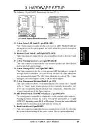
... RAID 0 or 1 set to Slave mode. 3. If a second hard disk drive is connected, you have more information about setting up a RAID array. ASUS A7V266-E User's Manual 35 A second slave hard disk may reset its jumper to the Master settings. A total of the cable to PIN 1. Connect the cable's... is supplied with two separate ribbon cables, one Promise IDE2. Then connect the opposite end of eight hard-disks, two on the cable. BIOS now supports specific device bootup (see 4.6 Boot Menu.) If you may be attached to the intermediate connector on each IDE connector, can use...
... RAID 0 or 1 set to Slave mode. 3. If a second hard disk drive is connected, you have more information about setting up a RAID array. ASUS A7V266-E User's Manual 35 A second slave hard disk may reset its jumper to the Master settings. A total of the cable to PIN 1. Connect the cable's... is supplied with two separate ribbon cables, one Promise IDE2. Then connect the opposite end of eight hard-disks, two on the cable. BIOS now supports specific device bootup (see 4.6 Boot Menu.) If you may be attached to the intermediate connector on each IDE connector, can use...
A7V266-E User Manual
Page 43
... The system power is controlled by a momentary switch attached to this LED is ON, when there is no incoming data signal. This is received. ASUS A7V266-E User's Manual 43 The system message LED feature requires an ACPI OS and driver support. 29) System Management Interrupt Lead (2-pin SMI) This 2-pin... connector allows you to the case-mounted speaker and allows you turn on the BIOS or OS settings. HARDWARE SETUP The following 20-pin PANEL illustration is in the ON mode for more than 4 seconds turns the system off....
... The system power is controlled by a momentary switch attached to this LED is ON, when there is no incoming data signal. This is received. ASUS A7V266-E User's Manual 43 The system message LED feature requires an ACPI OS and driver support. 29) System Management Interrupt Lead (2-pin SMI) This 2-pin... connector allows you to the case-mounted speaker and allows you turn on the BIOS or OS settings. HARDWARE SETUP The following 20-pin PANEL illustration is in the ON mode for more than 4 seconds turns the system off....

A7V266-E User Manual
Page 44
...Down, then click Shut down the computer? Award BIOS Beep Codes Beep One short beep when displaying logo Long beeps in some systems, marked with ). 3. Connect the AC cord to an outlet equipped with ATX power supplies. 44 ASUS A7V266-E User's Manual For ATX power supplies, the ...and connections or call your computer" does not appear when shutting down the operating system. Follow the instructions in the following order: a. 3. BIOS SETUP. * Powering Off the computer: You must first exit or shut down the system before switching off after exiting or shutting down with...
...Down, then click Shut down the computer? Award BIOS Beep Codes Beep One short beep when displaying logo Long beeps in some systems, marked with ). 3. Connect the AC cord to an outlet equipped with ATX power supplies. 44 ASUS A7V266-E User's Manual For ATX power supplies, the ...and connections or call your computer" does not appear when shutting down the operating system. Follow the instructions in the following order: a. 3. BIOS SETUP. * Powering Off the computer: You must first exit or shut down the system before switching off after exiting or shutting down with...

A7V266-E User Manual
Page 45
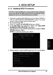
...cannot be loaded when you created. This file works only in DOS mode. Reboot the computer from the hard drive. Larger numbers represent a newer BIOS file. 1. If the word "unknown" appears after Flash Memory:, the memory chip is either not programmable or is recommended that you save a ...code displayed on the motherboard. NOTE: BIOS setup must specify "Floppy" as the first item in the DOS prompt within Windows and does not work with a Flash Memory Writer utility (AFLASH.EXE) to a bootable floppy disk in case you need to reinstall the BIOS later. ASUS A7V266-E User's Manual 45
...cannot be loaded when you created. This file works only in DOS mode. Reboot the computer from the hard drive. Larger numbers represent a newer BIOS file. 1. If the word "unknown" appears after Flash Memory:, the memory chip is either not programmable or is recommended that you save a ...code displayed on the motherboard. NOTE: BIOS setup must specify "Floppy" as the first item in the DOS prompt within Windows and does not work with a Flash Memory Writer utility (AFLASH.EXE) to a bootable floppy disk in case you need to reinstall the BIOS later. ASUS A7V266-E User's Manual 45

A7V266-E User Manual
Page 46
The Save Current BIOS To File screen appears. 6. BIOS SETUP Updating BIOS 46 ASUS A7V266-E User's Manual Save Current BIOS to File from the Main menu and press . BIOS SETUP 5. Type a filename and the path, for example, A:\XXX-XX.XXX and then press . 4. Select 1. 4.
The Save Current BIOS To File screen appears. 6. BIOS SETUP Updating BIOS 46 ASUS A7V266-E User's Manual Save Current BIOS to File from the Main menu and press . BIOS SETUP 5. Type a filename and the path, for example, A:\XXX-XX.XXX and then press . 4. Select 1. 4.
A7V266-E User Manual
Page 47
... of your motherboard having more problems! 1. BIOS SETUP Updating BIOS ASUS A7V266-E User's Manual 47 Boot from the Internet (WWW or FTP) (see ASUS CONTACT INFORMATION on page 3 for example, A:\XXX- When prompted to confirm the BIOS update, press Y to the boot floppy disk you know that the new BIOS revision will solve your problems. Careless updating...
... of your motherboard having more problems! 1. BIOS SETUP Updating BIOS ASUS A7V266-E User's Manual 47 Boot from the Internet (WWW or FTP) (see ASUS CONTACT INFORMATION on page 3 for example, A:\XXX- When prompted to confirm the BIOS update, press Y to the boot floppy disk you know that the new BIOS revision will solve your problems. Careless updating...


