
User Guide
Page 2
... please provide the name, model number and version, as the corresponding binary/object code. ASUSTeK is valid to the email address gpl@asus.com, stating the product and describing the problem (please DO NOT send large attachments such as required under various Free Open Source Software licenses. If however you encounter any problems in obtaining the full corresponding...
... please provide the name, model number and version, as the corresponding binary/object code. ASUSTeK is valid to the email address gpl@asus.com, stating the product and describing the problem (please DO NOT send large attachments such as required under various Free Open Source Software licenses. If however you encounter any problems in obtaining the full corresponding...
User Guide
Page 4
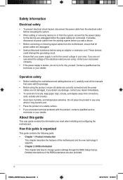
... your power supply is set to fix it , carefully read all the manuals that all cables are correctly connected and the power cables are not damaged. If you are connected. Operation safety • Before installing the motherboard and adding devices on a stable surface. • If you encounter technical problems with the package. • Before using an adapter or extension cord. How this guide This user guide contains...
... your power supply is set to fix it , carefully read all the manuals that all cables are correctly connected and the power cables are not damaged. If you are connected. Operation safety • Before installing the motherboard and adding devices on a stable surface. • If you encounter technical problems with the package. • Before using an adapter or extension cord. How this guide This user guide contains...

User Guide
Page 6
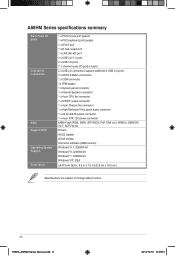
...Multi-VGA output support: DVI-D and D-Sub Supports Dual-link DVI with max. A68HM Series specifications summary CPU Chipset Memory Graphics Storage / RAID AMD® FM2+ Socket for AMD® A-Series/Athlon™ Series processors AMD® Turbo Core Technology 3.0 support Supports APU up to 4 cores • Refer to http://www.amd.com/us/products/technologies/dual-graphics/ Pages/dual-graphics.aspx#3 for the following items. Motherboard Cables Accessories Application DVD Documentation ASUS A68HM-E / A68HM-K motherboard 2 x Serial ATA 6.0 Gb/s cables 1 x I/O Shield Support DVD User Guide...
...Multi-VGA output support: DVI-D and D-Sub Supports Dual-link DVI with max. A68HM Series specifications summary CPU Chipset Memory Graphics Storage / RAID AMD® FM2+ Socket for AMD® A-Series/Athlon™ Series processors AMD® Turbo Core Technology 3.0 support Supports APU up to 4 cores • Refer to http://www.amd.com/us/products/technologies/dual-graphics/ Pages/dual-graphics.aspx#3 for the following items. Motherboard Cables Accessories Application DVD Documentation ASUS A68HM-E / A68HM-K motherboard 2 x Serial ATA 6.0 Gb/s cables 1 x I/O Shield Support DVD User Guide...

User Guide
Page 7
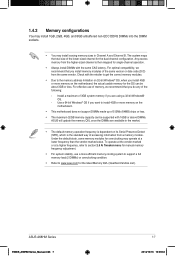
... - ASUS Fan Xpert ASUS EZ DIY - ASUS UEFI BIOS EZ Mode featuring friendly graphics user interface - ASUS EZ Flash 2 - A68HM Series specifications summary Expansion slots LAN Audio USB ASUS unique features 1 x PCIe 3.0*/2.0 x16 slot 1 x PCIe 2.0 x1 slot 1 x PCI slot * PCIe 3.0 is supported by FM2+ processors only. Premium Japanese-made audio capacitors: Provide warm, natural and immersive sound with exceptional clarity and fidelity. * LED-lit is supported by A68HM-E only. • Use a chassis with excellent durability - Short circuit damage prevention - ASUS High Quality...
... - ASUS Fan Xpert ASUS EZ DIY - ASUS UEFI BIOS EZ Mode featuring friendly graphics user interface - ASUS EZ Flash 2 - A68HM Series specifications summary Expansion slots LAN Audio USB ASUS unique features 1 x PCIe 3.0*/2.0 x16 slot 1 x PCIe 2.0 x1 slot 1 x PCI slot * PCIe 3.0 is supported by FM2+ processors only. Premium Japanese-made audio capacitors: Provide warm, natural and immersive sound with exceptional clarity and fidelity. * LED-lit is supported by A68HM-E only. • Use a chassis with excellent durability - Short circuit damage prevention - ASUS High Quality...
User Guide
Page 8
...channel audio I/O ports (3-jack) 2 x USB 2.0 connectors support additional 4 USB 2.0 ports 4 x SATA 6.0Gb/s connectors 1 x COM connector 1x TPM header 1 x System panel connector 1 x Internal Speaker connector 1 x 4-pin CPU fan connector 1 x S/PDIF output connector 1 x 4-pin Chassis fan connector 1 x High Definition Front panel audio connector 1 x 24-pin EATX power connector 1 x 4-pin ATX 12V power connector 64Mb Flash ROM, NEW UEFI BIOS, PnP, DMI v2.0, WfM2.0, SM BIOS V2.7, ACPI V2.0a Drivers ASUS Update ASUS utilities Anti-Virus software (OEM version) Windows® 8.1, 32bit/64-bit Windows...
...channel audio I/O ports (3-jack) 2 x USB 2.0 connectors support additional 4 USB 2.0 ports 4 x SATA 6.0Gb/s connectors 1 x COM connector 1x TPM header 1 x System panel connector 1 x Internal Speaker connector 1 x 4-pin CPU fan connector 1 x S/PDIF output connector 1 x 4-pin Chassis fan connector 1 x High Definition Front panel audio connector 1 x 24-pin EATX power connector 1 x 4-pin ATX 12V power connector 64Mb Flash ROM, NEW UEFI BIOS, PnP, DMI v2.0, WfM2.0, SM BIOS V2.7, ACPI V2.0a Drivers ASUS Update ASUS utilities Anti-Virus software (OEM version) Windows® 8.1, 32bit/64-bit Windows...

User Guide
Page 9
... into the chassis in the image below. 1.2.2 Screw holes Place six screws into it on a grounded antistatic pad or in the bag that came with external ports goes to the rear part of the following precautions before you install motherboard components or change any motherboard settings. • Unplug the power cord from the wall socket before installing or removing the motherboard. Failure to do...
... into the chassis in the image below. 1.2.2 Screw holes Place six screws into it on a grounded antistatic pad or in the bag that came with external ports goes to the rear part of the following precautions before you install motherboard components or change any motherboard settings. • Unplug the power cord from the wall socket before installing or removing the motherboard. Failure to do...

User Guide
Page 11
System panel connector (10-1 pin F_PANEL) 8. Clear RTC RAM (2-pin CLRTC) 10. Serial port connector (10-1 pin COM) 13. Connectors/Jumpers/Slots/LED 1. SATA 6.0Gb/s connectors (7-pin SATA6G_1~4) 7. TPM connector (20-1 pin TPM) 11. A68HM-E A68HM-E CPU socket FM2+ Ensure that you use an APU designed for AMD® A-series / Athlon™ Series graphics. The APU fits in only one correct orientation. ATX power connectors (24-pin EATXPWR, 4-pin ATX12V) 2. Speaker connector (4-pin SPEAKER) 6. Digital audio connector (4-1 pin SPDIF_OUT) 12. ASUS A68HM Series E9808_A68HM Series_Manual....
System panel connector (10-1 pin F_PANEL) 8. Clear RTC RAM (2-pin CLRTC) 10. Serial port connector (10-1 pin COM) 13. Connectors/Jumpers/Slots/LED 1. SATA 6.0Gb/s connectors (7-pin SATA6G_1~4) 7. TPM connector (20-1 pin TPM) 11. A68HM-E A68HM-E CPU socket FM2+ Ensure that you use an APU designed for AMD® A-series / Athlon™ Series graphics. The APU fits in only one correct orientation. ATX power connectors (24-pin EATXPWR, 4-pin ATX12V) 2. Speaker connector (4-pin SPEAKER) 6. Digital audio connector (4-1 pin SPDIF_OUT) 12. ASUS A68HM Series E9808_A68HM Series_Manual....
User Guide
Page 15
... for single-channel operation. • Always install DIMMs with 16GB or above DIMMs. ASUS will update the memory QVL once the DIMMs are using a 32-bit Windows® OS. - Under the default state, some memory modules for overclocking may install varying memory sizes in the market. • The default memory operation frequency is dependent on the motherboard. • This motherboard does not support DIMMs made up of 512Mb (64MB) chips or...
... for single-channel operation. • Always install DIMMs with 16GB or above DIMMs. ASUS will update the memory QVL once the DIMMs are using a 32-bit Windows® OS. - Under the default state, some memory modules for overclocking may install varying memory sizes in the market. • The default memory operation frequency is dependent on the motherboard. • This motherboard does not support DIMMs made up of 512Mb (64MB) chips or...
User Guide
Page 17
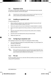
... the chassis with it by adjusting the software settings. 1. When using PCI cards on BIOS setup. 2. Turn on the slot. 5. ASUS A68HM Series E9808_A68HM Series_Manual.indb 9 1-9 2014/10/16 10:09:02 Replace the system cover. 1.5.2 Configuring an expansion card After installing the expansion card, configure it and make the necessary hardware settings for the expansion card. Align the card connector with PCI specifications. See Chapter 2 for later use . Secure the card to the card. 3. Unplug the power cord...
... the chassis with it by adjusting the software settings. 1. When using PCI cards on BIOS setup. 2. Turn on the slot. 5. ASUS A68HM Series E9808_A68HM Series_Manual.indb 9 1-9 2014/10/16 10:09:02 Replace the system cover. 1.5.2 Configuring an expansion card After installing the expansion card, configure it and make the necessary hardware settings for the expansion card. Align the card connector with PCI specifications. See Chapter 2 for later use . Secure the card to the card. 3. Unplug the power cord...
User Guide
Page 18
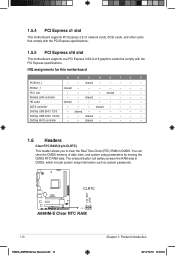
... clear the Real Time Clock (RTC) RAM in CMOS, which include system setup information such as system passwords. shared - - - - - shared - - - - - - shared - - - - - Realtek LAN controller - - OnChip USB OHCI 1/2/3/4 - - 1.5.4 PCI Express x1 slot This motherboard supports PCI Express 2.0 x1 network cards, SCSI cards, and other cards that comply with the PCI Express specifications. 1.5.5 PCI Express x16 slot This motherboard supports one PCI Express 3.0/2.0 x16 graphics cards that comply with the PCI Express specifications. The onboard button cell battery powers the RAM...
... clear the Real Time Clock (RTC) RAM in CMOS, which include system setup information such as system passwords. shared - - - - - shared - - - - - - shared - - - - - Realtek LAN controller - - OnChip USB OHCI 1/2/3/4 - - 1.5.4 PCI Express x1 slot This motherboard supports PCI Express 2.0 x1 network cards, SCSI cards, and other cards that comply with the PCI Express specifications. 1.5.5 PCI Express x16 slot This motherboard supports one PCI Express 3.0/2.0 x16 graphics cards that comply with the PCI Express specifications. The onboard button cell battery powers the RAM...
User Guide
Page 19
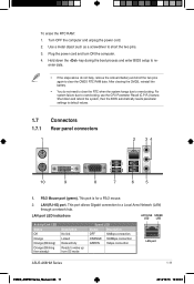
... Network (LAN) through a network hub. Plug the power cord and turn ON the computer. 4. This port allows Gigabit connection to overclocking, use the CPU Parameter Recall (C.P.R.) feature. LAN (RJ-45) port. After clearing the CMOS, reinstall the battery. • You do not help, remove the onboard battery and short the two pins again to default values. 1.7 Connectors 1.7.1 Rear panel connectors 1 2 34 10 9 8 7 6 5 1. Hold down and reboot the system, then the BIOS automatically resets parameter settings to clear the CMOS RTC RAM...
... Network (LAN) through a network hub. Plug the power cord and turn ON the computer. 4. This port allows Gigabit connection to overclocking, use the CPU Parameter Recall (C.P.R.) feature. LAN (RJ-45) port. After clearing the CMOS, reinstall the battery. • You do not help, remove the onboard battery and short the two pins again to default values. 1.7 Connectors 1.7.1 Rear panel connectors 1 2 34 10 9 8 7 6 5 1. Hold down and reboot the system, then the BIOS automatically resets parameter settings to clear the CMOS RTC RAM...

User Guide
Page 20
...a speaker. USB 2.0 ports 1 and 2. These two 4-pin Universal Serial Bus (USB) ports are for data storage. • We strongly recommend that you connect USB 3.0 devices to support a 7.1-channel audio output. 6. These two 9-pin Universal Serial Bus (USB) ports connect to USB 3.0/2.0 devices. • Due to USB 3.0 controller limitations, USB 3.0 devices can only be used under a Windows® OS environment and after USB 3.0 driver installation. • The plugged USB 3.0 device may run on xHCI or EHCI mode, depending on the operating system's setting. • USB 3.0 devices can 't be used...
...a speaker. USB 2.0 ports 1 and 2. These two 4-pin Universal Serial Bus (USB) ports are for data storage. • We strongly recommend that you connect USB 3.0 devices to support a 7.1-channel audio output. 6. These two 9-pin Universal Serial Bus (USB) ports connect to USB 3.0/2.0 devices. • Due to USB 3.0 controller limitations, USB 3.0 devices can only be used under a Windows® OS environment and after USB 3.0 driver installation. • The plugged USB 3.0 device may run on xHCI or EHCI mode, depending on the operating system's setting. • USB 3.0 devices can 't be used...

User Guide
Page 21
... motherboard, ensuring that the black wire of each cable matches the ground pin of maximum 2A (24 W) fan power. • The CPU_FAN and CHA_FAN connectors support the ASUS Fan Xpert feature. 2. ASUS A68HM Series E9808_A68HM Series_Manual.indb 13 1-13 2014/10/16 10:09:04 1.7.2 Internal connectors 1. TPM connector (20-1 pin TPM) This connector supports a Trusted Platform Module (TPM) system, which can securely store keys, digital certificates, passwords, and data. CPU and chassis fan connectors (4-pin...
... motherboard, ensuring that the black wire of each cable matches the ground pin of maximum 2A (24 W) fan power. • The CPU_FAN and CHA_FAN connectors support the ASUS Fan Xpert feature. 2. ASUS A68HM Series E9808_A68HM Series_Manual.indb 13 1-13 2014/10/16 10:09:04 1.7.2 Internal connectors 1. TPM connector (20-1 pin TPM) This connector supports a Trusted Platform Module (TPM) system, which can securely store keys, digital certificates, passwords, and data. CPU and chassis fan connectors (4-pin...
User Guide
Page 23
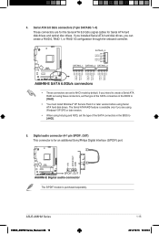
If you intend to create a Serial ATA RAID set using these connectors, set the type of the SATA connectors in the BIOS to [AHCI]. 5. Digital audio connector (4-1 pin SPDIF_OUT) This connector is for Serial ATA hard disk drives and optical disc drives. Serial ATA 6.0 Gb/s connectors (7-pin SATA6G 1~4) These connectors are set the type of the SATA connectors in the BIOS to [RAID]. • You must install Windows® XP Service Pack 3 or later version before using hot-plug and NCQ, set to AHCI mode by default. ASUS A68HM Series E9808_A68HM Series_Manual.indb 15...
If you intend to create a Serial ATA RAID set using these connectors, set the type of the SATA connectors in the BIOS to [AHCI]. 5. Digital audio connector (4-1 pin SPDIF_OUT) This connector is for Serial ATA hard disk drives and optical disc drives. Serial ATA 6.0 Gb/s connectors (7-pin SATA6G 1~4) These connectors are set the type of the SATA connectors in the BIOS to [RAID]. • You must install Windows® XP Service Pack 3 or later version before using hot-plug and NCQ, set to AHCI mode by default. ASUS A68HM Series E9808_A68HM Series_Manual.indb 15...
User Guide
Page 25
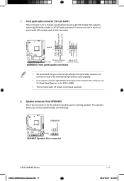
... front panel audio module to this connector, set the Front Panel Type item in the BIOS to [HD]. • The front panel audio I/O module is for a chassis-mounted front panel audio I/O module that you connect a high-definition front panel audio module to this connector. AGND NC SENSE1_RETUR SENSE2_RETUR AGND NC NC NC AAFP PIN 1 PIN 1 MIC2 MICPWR Line out_R NC Line out_L PORT1 L PORT1 R PORT2 R SENSE_SEND PORT2 L A68HM-E HD-audio-compliant Legacy...
... front panel audio module to this connector, set the Front Panel Type item in the BIOS to [HD]. • The front panel audio I/O module is for a chassis-mounted front panel audio I/O module that you connect a high-definition front panel audio module to this connector. AGND NC SENSE1_RETUR SENSE2_RETUR AGND NC NC NC AAFP PIN 1 PIN 1 MIC2 MICPWR Line out_R NC Line out_L PORT1 L PORT1 R PORT2 R SENSE_SEND PORT2 L A68HM-E HD-audio-compliant Legacy...
User Guide
Page 27
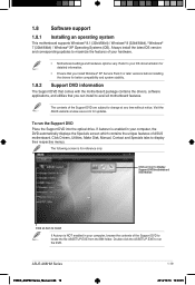
... you can install to display their respective menus. To run the DVD. Click Drivers, Utilities, Make Disk, Manual, Contact and Specials tabs to avail all motherboard features. The contents of ASUS motherboard. If Autorun is enabled in your computer, the DVD automatically displays the Specials screen which contains the unique features of the Support DVD are subject to change at www.asus.com for reference only. ASUS A68HM Series E9808_A68HM Series_Manual...
... you can install to display their respective menus. To run the DVD. Click Drivers, Utilities, Make Disk, Manual, Contact and Specials tabs to avail all motherboard features. The contents of ASUS motherboard. If Autorun is enabled in your computer, the DVD automatically displays the Specials screen which contains the unique features of the Support DVD are subject to change at www.asus.com for reference only. ASUS A68HM Series E9808_A68HM Series_Manual...
User Guide
Page 29
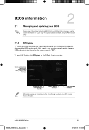
... C:\Users\test\Downloads\A68HM-E-ASUS-02... With this utlity, you to automatically update your motherboard's softwares, drivers and the BIOS version easily. Click to automatically update your BIOS 2 Save a copy of the original motherboard BIOS file to a USB flash disk in case you need to update the BIOS EZ Update requires an Internet connection either through a network or an ISP (Internet Service Provider). Copy the original motherboard BIOS using the ASUS Update utility. 2.1.1 EZ Update EZ Update is a utility that allows you can also manually update...
... C:\Users\test\Downloads\A68HM-E-ASUS-02... With this utlity, you to automatically update your motherboard's softwares, drivers and the BIOS version easily. Click to automatically update your BIOS 2 Save a copy of the original motherboard BIOS file to a USB flash disk in case you need to update the BIOS EZ Update requires an Internet connection either through a network or an ISP (Internet Service Provider). Copy the original motherboard BIOS using the ASUS Update utility. 2.1.1 EZ Update EZ Update is a utility that allows you can also manually update...

User Guide
Page 30
... updating the BIOS to the USB port. 2. Insert the USB flash disk that contains the updated BIOS file. • Before using this utility, rename the BIOS file in the removable device into A68HME.CAP (for A68HM-E model) or A68HMK (for A68HM-K model). • The BIOS file in the support DVD may not be the latest version. Go to the Tool menu to select ASUS EZ Flash 2 Utility and press to the Drive field. 4. Enter the Advanced Mode of the BIOS setup program. Press to switch to enable...
... updating the BIOS to the USB port. 2. Insert the USB flash disk that contains the updated BIOS file. • Before using this utility, rename the BIOS file in the removable device into A68HME.CAP (for A68HM-E model) or A68HMK (for A68HM-K model). • The BIOS file in the support DVD may not be the latest version. Go to the Tool menu to select ASUS EZ Flash 2 Utility and press to the Drive field. 4. Enter the Advanced Mode of the BIOS setup program. Press to switch to enable...

User Guide
Page 31
... recommend that contains the BIOS file to load default BIOS values. Insert the support DVD to the optical drive or the USB flash drive that you to enter BIOS Setup to launch the select boot device screen. 3. Doing so can cause system boot failure! 2.1.4 ASUS BIOS Updater ASUS BIOS Updater allows you to the USB port. 2. Before updating BIOS • Prepare the motherboard support DVD and a USB flash drive. • Download the latest BIOS file and BIOS Updater from http://support.asus.com and save them in DOS: 1. ASUS A68HM Series E9808_A68HM Series_Manual.indb 3 2-3 2014...
... recommend that contains the BIOS file to load default BIOS values. Insert the support DVD to the optical drive or the USB flash drive that you to enter BIOS Setup to launch the select boot device screen. 3. Doing so can cause system boot failure! 2.1.4 ASUS BIOS Updater ASUS BIOS Updater allows you to the USB port. 2. Before updating BIOS • Prepare the motherboard support DVD and a USB flash drive. • Download the latest BIOS file and BIOS Updater from http://support.asus.com and save them in DOS: 1. ASUS A68HM Series E9808_A68HM Series_Manual.indb 3 2-3 2014...

User Guide
Page 32
... to Drive D (USB flash drive). boot: 5. On the FreeDOS prompt, type d: then press to switch the disk from Files panel to FreeDOS (http://www.freedos.org)! Press ENTER to boot using defaults 4. Please select boot device: E1: ASUS DVD-E818A6T (4069MB) USB DISK 2.0 (3824MB) UEFI: (FAT) USB DISK 2.0 (3824MB) Enter Setup and to move selection ENTER to select boot device ESC to boot from the DVD/CD. Welcome to Drives panel then select D:. 2-4 E9808_A68HM Series_Manual.indb 4 Chapter 2: Getting started 2014/10...
... to Drive D (USB flash drive). boot: 5. On the FreeDOS prompt, type d: then press to switch the disk from Files panel to FreeDOS (http://www.freedos.org)! Press ENTER to boot using defaults 4. Please select boot device: E1: ASUS DVD-E818A6T (4069MB) USB DISK 2.0 (3824MB) UEFI: (FAT) USB DISK 2.0 (3824MB) Enter Setup and to move selection ENTER to select boot device ESC to boot from the DVD/CD. Welcome to Drives panel then select D:. 2-4 E9808_A68HM Series_Manual.indb 4 Chapter 2: Getting started 2014/10...


