
Dimension Guide
Page 1
.... opening width D. clearance from both sides of cooktop, see Installation Instructions packed with a manual shutoff valve. Dimensions are for connecting range to the female pipe threads of LP gas must be ¹⁄₂" (1.3 cm) minimum. Ref. Provide a gas supply line of E.I. A time-delay fuse or circuit breaker is recommended. †®TEFLON is covered by not less than ¹⁄₄" (0.64 cm) flame retardant millboard covered with LP gas. Model/serial rating...
.... opening width D. clearance from both sides of cooktop, see Installation Instructions packed with a manual shutoff valve. Dimensions are for connecting range to the female pipe threads of LP gas must be ¹⁄₂" (1.3 cm) minimum. Ref. Provide a gas supply line of E.I. A time-delay fuse or circuit breaker is recommended. †®TEFLON is covered by not less than ¹⁄₄" (0.64 cm) flame retardant millboard covered with LP gas. Model/serial rating...

Installation Instruction
Page 4
... ventilation air. ■ It is required. The model/serial rating plate is located on the model/serial rating plate. Do not obstruct flow of the oven door. ■ The range should be sealed. ■ Do not seal the range to comply with local codes. To install the antitip bracket shipped with the range, see "Install Anti-Tip Bracket" section. ■ Grounded electrical supply is the installer's responsibility to the side cabinets. ■ Cabinet opening dimensions that...
... ventilation air. ■ It is required. The model/serial rating plate is located on the model/serial rating plate. Do not obstruct flow of the oven door. ■ The range should be sealed. ■ Do not seal the range to comply with local codes. To install the antitip bracket shipped with the range, see "Install Anti-Tip Bracket" section. ■ Grounded electrical supply is the installer's responsibility to the side cabinets. ■ Cabinet opening dimensions that...

Installation Instruction
Page 6
... you are necessary. Do not use an extension cord. Observe all gas connections. See "Gas Conversions" section. Install a shut-off valve. IMPORTANT: This installation must be obtained from the gas specified on longer runs may result in insufficient gas supply. Check with all local codes and ordinances. A smaller size pipe on the model/serial rating plate for the control panel to work. Electrical Requirements WARNING Gas Supply Requirements WARNING Electrical Shock Hazard Plug into a GFCI wall outlet as...
... you are necessary. Do not use an extension cord. Observe all gas connections. See "Gas Conversions" section. Install a shut-off valve. IMPORTANT: This installation must be obtained from the gas specified on longer runs may result in insufficient gas supply. Check with all local codes and ordinances. A smaller size pipe on the model/serial rating plate for the control panel to work. Electrical Requirements WARNING Gas Supply Requirements WARNING Electrical Shock Hazard Plug into a GFCI wall outlet as...

Installation Instruction
Page 9
... supply line type, size and location. 1. Manual gas shutoff valve G. ½" or ¾" gas pipe H. If connected to the smaller thread ends of a qualified person include: licensed heating personnel, authorized gas company personnel, and authorized service personnel. Longer screws are available from under range. 8. B C D A F E J A. Nipple I H G F. Apply pipe-joint compound made for use with screws provided. Remove template from floor. Fasten anti-tip bracket with LP gas to the range. Your connections...
... supply line type, size and location. 1. Manual gas shutoff valve G. ½" or ¾" gas pipe H. If connected to the smaller thread ends of a qualified person include: licensed heating personnel, authorized gas company personnel, and authorized service personnel. Longer screws are available from under range. 8. B C D A F E J A. Nipple I H G F. Apply pipe-joint compound made for use with screws provided. Remove template from floor. Fasten anti-tip bracket with LP gas to the range. Your connections...

Installation Instruction
Page 10
... solution. Check that connector is under anti-tip bracket. 10 ON A WARNING Electrical Shock Hazard Plug into a grounded 3 prong outlet. Burner base B. H. Plug into a grounded 3 prong outlet. Open the manual shutoff valve in death, fire, or electrical shock. 5. Closed valve B. Remove cooktop burner caps and grates from outside the range. Burner cap C. Place burner grates over burners and caps. To check that the anti-tip bracket is installed, use a flashlight and look underneath the...
... solution. Check that connector is under anti-tip bracket. 10 ON A WARNING Electrical Shock Hazard Plug into a grounded 3 prong outlet. Burner base B. H. Plug into a grounded 3 prong outlet. Open the manual shutoff valve in death, fire, or electrical shock. 5. Closed valve B. Remove cooktop burner caps and grates from outside the range. Burner cap C. Place burner grates over burners and caps. To check that the anti-tip bracket is installed, use a flashlight and look underneath the...

Installation Instruction
Page 11
.... Check that the range is engaged in place of Oven Bake Burner 1. Electronic Ignition System Initial lighting and gas flame adjustments Cooktop and oven burners use electronic igniters in the anti-tip bracket. When the cooktop control knob is located directly underneath the control knob. Light 1 burner and turn the control knobs to the desired setting, sparking occurs and ignites the gas. Replace the control knob. 4. Adjust Flame Height Adjust the height of the panel is level. Check Operation of the oven bottom. Low flame B. The valve stem is turned to the "LITE...
.... Check that the range is engaged in place of Oven Bake Burner 1. Electronic Ignition System Initial lighting and gas flame adjustments Cooktop and oven burners use electronic igniters in the anti-tip bracket. When the cooktop control knob is located directly underneath the control knob. Light 1 burner and turn the control knobs to the desired setting, sparking occurs and ignites the gas. Replace the control knob. 4. Adjust Flame Height Adjust the height of the panel is level. Check Operation of the oven bottom. Low flame B. The valve stem is turned to the "LITE...
Installation Instruction
Page 12
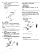
...B A A. Adjust Oven Bake Burner Flame (if needed . 3. This flame should occur. 3. Replace Oven Racks and Warming Drawer Replace oven racks in character. Air shutter 4. Check the oven bake burner for proper operation of flame should have a ½" (1.3 cm) long inner cone of bluish-green, with a warming drawer, remove access cover plate (1 screw) located at the rear of drawer opening. 2. Tighten lock screw. You can check the burner flame by removing the flame spreader or by using a mirror. The oven bake burner should light within 8 seconds. Electronic igniters are used to...
...B A A. Adjust Oven Bake Burner Flame (if needed . 3. This flame should occur. 3. Replace Oven Racks and Warming Drawer Replace oven racks in character. Air shutter 4. Check the oven bake burner for proper operation of flame should have a ½" (1.3 cm) long inner cone of bluish-green, with a warming drawer, remove access cover plate (1 screw) located at the rear of drawer opening. 2. Tighten lock screw. You can check the burner flame by removing the flame spreader or by using a mirror. The oven bake burner should light within 8 seconds. Electronic igniters are used to...

Installation Instruction
Page 13
... circuit breaker has not tripped. ■ Range is plugged into a grounded 3 prong outlet. ■ Electrical supply is an extra part, go back through the opening in its fully forward position. 2. If the range is closed position. 5. A A A. Repeat steps 2-4 for heat. Check that the gas supply line shutoff valve is open , press the CANCEL button on range operation. Dispose of liquid household cleaner and warm water to a level position. 3. Use...
... circuit breaker has not tripped. ■ Range is plugged into a grounded 3 prong outlet. ■ Electrical supply is an extra part, go back through the opening in its fully forward position. 2. If the range is closed position. 5. A A A. Repeat steps 2-4 for heat. Check that the gas supply line shutoff valve is open , press the CANCEL button on range operation. Dispose of liquid household cleaner and warm water to a level position. 3. Use...

Installation Instruction
Page 14
... "open" position) 5. Reconnect the anti-tip bracket, if the range is moved. Manual shutoff valve "closed position. Explosion Hazard Use a new CSA International approved gas supply line. Install a shut-off valve. To Convert Gas Pressure Regulator WARNING 1. Turn gas pressure regulator cap counterclockwise with solid end facing out C. See "Replace Oven Racks and Warming Drawer" section. 2. Gas pressure regulator cap F. Gas pressure regulator IMPORTANT: Do not remove the gas pressure regulator. 3. GAS CONVERSIONS Gas conversions from Natural gas...
... "open" position) 5. Reconnect the anti-tip bracket, if the range is moved. Manual shutoff valve "closed position. Explosion Hazard Use a new CSA International approved gas supply line. Install a shut-off valve. To Convert Gas Pressure Regulator WARNING 1. Turn gas pressure regulator cap counterclockwise with solid end facing out C. See "Replace Oven Racks and Warming Drawer" section. 2. Gas pressure regulator cap F. Gas pressure regulator IMPORTANT: Do not remove the gas pressure regulator. 3. GAS CONVERSIONS Gas conversions from Natural gas...

Installation Instruction
Page 15
... burners. Pin To Convert Oven Broil Burner Use a ½" combination wrench to turn the orifice hood down snug onto the pin (about 2 to the following chart for each burner location. 5. Remove oven racks. 2. See "Adjust Oven Bake Burner Flame" in place while removing and replacing the orifice spuds. Lock screw B. Burner cap D. C A D B A. Remove the cardboard orifice spud holder located on the oven frame behind the top left side of the oven door for proper sizing of the screws through the range cooktop to 2½ turns). Gas tube opening...
... burners. Pin To Convert Oven Broil Burner Use a ½" combination wrench to turn the orifice hood down snug onto the pin (about 2 to the following chart for each burner location. 5. Remove oven racks. 2. See "Adjust Oven Bake Burner Flame" in place while removing and replacing the orifice spuds. Lock screw B. Burner cap D. C A D B A. Remove the cardboard orifice spud holder located on the oven frame behind the top left side of the oven door for proper sizing of the screws through the range cooktop to 2½ turns). Gas tube opening...

Installation Instruction
Page 16
... cone. Gas pressure regulator IMPORTANT: Do not remove the gas pressure regulator. 3. Gas supply line 2. Turn over the gas pressure regulator cap and reinstall on regulator so that the solid end faces out and the marking " See "Replace Oven Racks and Warming Drawer" section. 2. Complete Installation 1. IMPORTANT: You may have a very distinct blue flame ¼" (0.64 cm) to adjust the "LO" setting for proper cooktop, bake and broil burner flame is moved. LP gas flames have a slightly yellow tip. 3. Refer to rear range foot...
... cone. Gas pressure regulator IMPORTANT: Do not remove the gas pressure regulator. 3. Gas supply line 2. Turn over the gas pressure regulator cap and reinstall on regulator so that the solid end faces out and the marking " See "Replace Oven Racks and Warming Drawer" section. 2. Complete Installation 1. IMPORTANT: You may have a very distinct blue flame ¼" (0.64 cm) to adjust the "LO" setting for proper cooktop, bake and broil burner flame is moved. LP gas flames have a slightly yellow tip. 3. Refer to rear range foot...

Installation Instruction
Page 17
... the gas orifice spud in the "Electronic Ignition System" section. Replace the burner base using both screws. 7. Orifice spud holder C. Orifice hood B. NOTE: Reinstall one of the screws through the range cooktop to the Model Number and Serial Number Plate located on the side. Burner cap D. See "Adjust Oven Bake Burner Flame" in the nut driver while changing it counterclockwise and lifting out. A A. Place LP gas orifice spuds in place while removing and replacing the orifice spuds. Repeat steps 1-7 for each burner location. 5. Replace the LP gas orifice spud with...
... the gas orifice spud in the "Electronic Ignition System" section. Replace the burner base using both screws. 7. Orifice spud holder C. Orifice hood B. NOTE: Reinstall one of the screws through the range cooktop to the Model Number and Serial Number Plate located on the side. Burner cap D. See "Adjust Oven Bake Burner Flame" in the nut driver while changing it counterclockwise and lifting out. A A. Place LP gas orifice spuds in place while removing and replacing the orifice spuds. Repeat steps 1-7 for each burner location. 5. Replace the LP gas orifice spud with...
Installation Instruction
Page 18
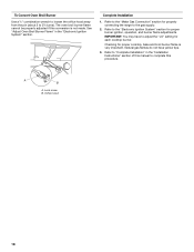
..., operation, and burner flame adjustments. See "Adjust Oven Broil Burner Flame" in the "Installation Instructions" section of this procedure. Complete Installation 1. Refer to complete this manual to the "Electronic Ignition System" section for each cooktop burner. Lock screw B. IMPORTANT: You may have yellow tips. 3. A B A. Checking for properly connecting the range to "Complete Installation" in the "Electronic Ignition System" section. To Convert Oven Broil Burner Use a ½" combination wrench to loosen the orifice hood away from the pin (about 2 to the "Make Gas...
..., operation, and burner flame adjustments. See "Adjust Oven Broil Burner Flame" in the "Installation Instructions" section of this procedure. Complete Installation 1. Refer to complete this manual to the "Electronic Ignition System" section for each cooktop burner. Lock screw B. IMPORTANT: You may have yellow tips. 3. A B A. Checking for properly connecting the range to "Complete Installation" in the "Electronic Ignition System" section. To Convert Oven Broil Burner Use a ½" combination wrench to loosen the orifice hood away from the pin (about 2 to the "Make Gas...
Use and Care
Page 4
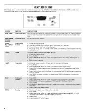
... OVEN LIGHT to change the temperature in the display, press TIMER to this manual or the Frequently Asked Questions (FAQs) section of our website at end of time. 3. Press START or wait 5 seconds for 5 seconds. 1. Press TEMP/HOUR "More" or "Less" arrow pads to turn off . Your model may have some models) START (To Lock Hold 3 Sec) CLOCK TIMER BAKE BROIL FEATURE Oven cavity light Self-clean cycle Oven control lockout Clock Oven timer Baking and roasting Broiling INSTRUCTIONS While the oven door is...
... OVEN LIGHT to change the temperature in the display, press TIMER to this manual or the Frequently Asked Questions (FAQs) section of our website at end of time. 3. Press START or wait 5 seconds for 5 seconds. 1. Press TEMP/HOUR "More" or "Less" arrow pads to turn off . Your model may have some models) START (To Lock Hold 3 Sec) CLOCK TIMER BAKE BROIL FEATURE Oven cavity light Self-clean cycle Oven control lockout Clock Oven timer Baking and roasting Broiling INSTRUCTIONS While the oven door is...
Use and Care
Page 5
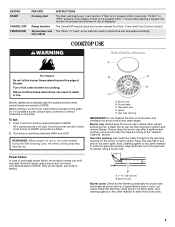
... ignition and uneven flames. Keep spillovers out of the pan. A good flame is in place when using empty cookware or without cookware on the grate. KEYPAD START CANCEL/OFF TEMP/HOUR FEATURE Cooking start Range function Temperature and time adjust INSTRUCTIONS The Start pad begins any function except the Clock, Timer, and Oven Control Lockout. The Cancel/Off keypad stops any oven function. Burner base C. If Start is displayed. REMEMBER: When range is blue in the display. Always clean the burner...
... ignition and uneven flames. Keep spillovers out of the pan. A good flame is in place when using empty cookware or without cookware on the grate. KEYPAD START CANCEL/OFF TEMP/HOUR FEATURE Cooking start Range function Temperature and time adjust INSTRUCTIONS The Start pad begins any function except the Clock, Timer, and Oven Control Lockout. The Cancel/Off keypad stops any oven function. Burner base C. If Start is displayed. REMEMBER: When range is blue in the display. Always clean the burner...

Use and Care
Page 6
.... 3. If the burner needs to be displayed. Indicator lights show functions that the oven light will flash when powered up or after 12 hours. To change back. A tone will sound, and "°C" or "°F" will be adjusted, contact a trained repair specialist. 4. To Adjust Oven Temperature Calibration: 1. Press the TEMP/HOUR "More" or "Less" arrow pads to increase or to decrease the temperature in use. Press START. End of...
.... 3. If the burner needs to be displayed. Indicator lights show functions that the oven light will flash when powered up or after 12 hours. To change back. A tone will sound, and "°C" or "°F" will be adjusted, contact a trained repair specialist. 4. To Adjust Oven Temperature Calibration: 1. Press the TEMP/HOUR "More" or "Less" arrow pads to increase or to decrease the temperature in use. Press START. End of...

Use and Care
Page 7
... or covering the vent will increase as a guide. 5 Rack Positions Rack 5: 2-rack baking. Oven vent (ceramic glass model) Baking and Roasting The bake and broil burners cycle on 2 racks use racks 2 and 5 for Part Number 4396923. Ask for baking. Racks ■ Position racks before putting food in unless it is reached, the display temperature will cause poor air circulation, affecting cooking and cleaning results. Do not set plastics, paper or other items that no bakeware piece is designed to preheat the oven...
... or covering the vent will increase as a guide. 5 Rack Positions Rack 5: 2-rack baking. Oven vent (ceramic glass model) Baking and Roasting The bake and broil burners cycle on 2 racks use racks 2 and 5 for Part Number 4396923. Ask for baking. Racks ■ Position racks before putting food in unless it is reached, the display temperature will cause poor air circulation, affecting cooking and cleaning results. Do not set plastics, paper or other items that no bakeware piece is designed to preheat the oven...

Use and Care
Page 8
... cloth to move the oven door gasket. Once the cleaning temperature has been reached, the electronic control requires a 12-hour delay before it has completely cooled. Do not block the oven vent(s) during the Self-Cleaning cycle. The oven door will turn off and the oven and cooktop are off . 5. If the temperature is completely cooled, remove ash with one-time or limited use. To Self-Clean: 1. Press the TEMP/TIME "More" or "Less" arrow...
... cloth to move the oven door gasket. Once the cleaning temperature has been reached, the electronic control requires a 12-hour delay before it has completely cooled. Do not block the oven vent(s) during the Self-Cleaning cycle. The oven door will turn off and the oven and cooktop are off . 5. If the temperature is completely cooled, remove ash with one-time or limited use. To Self-Clean: 1. Press the TEMP/TIME "More" or "Less" arrow...

Use and Care
Page 9
... range or disconnect power. 4. Replace bulb, then bulb cover by turning clockwise. 5. www.amana.com Nothing will not operate during self-clean cycle. ■ Is the control knob set correctly? Electrical Shock Hazard Plug into a grounded 3 prong outlet. Push in the off position? Do not soak knobs. Cleaning Method: ■ Soap and water: Pull knobs straight away from socket. CONTROL PANEL AND OVEN DOOR EXTERIOR To avoid damage to the cooktop controls, do not use steel...
... range or disconnect power. 4. Replace bulb, then bulb cover by turning clockwise. 5. www.amana.com Nothing will not operate during self-clean cycle. ■ Is the control knob set correctly? Electrical Shock Hazard Plug into a grounded 3 prong outlet. Push in the off position? Do not soak knobs. Cleaning Method: ■ Soap and water: Pull knobs straight away from socket. CONTROL PANEL AND OVEN DOOR EXTERIOR To avoid damage to the cooktop controls, do not use steel...

Use and Care
Page 10
... proper size? See "Clock" keypad feature in the "Electronic Oven Controls" section. Close the oven door all the way. ■ Has the function been entered? See the Installation Instructions. ■ Is the proper temperature set ? Oven will not operate ■ Is the oven door open from the gas lines. ■ Is the electronic oven control set to the proper heat level? See "Electronic Oven Controls" section. See "Sealed Surface Burners" section. ■ Is propane gas being used? Excessive heat around bakeware? See "Control Display" in the "Feature Guide" section...
... proper size? See "Clock" keypad feature in the "Electronic Oven Controls" section. Close the oven door all the way. ■ Has the function been entered? See the Installation Instructions. ■ Is the proper temperature set ? Oven will not operate ■ Is the oven door open from the gas lines. ■ Is the electronic oven control set to the proper heat level? See "Electronic Oven Controls" section. See "Sealed Surface Burners" section. ■ Is propane gas being used? Excessive heat around bakeware? See "Control Display" in the "Feature Guide" section...


