Aspire X1200 / X3200 Service Guide
Page 5
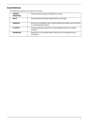
v NOTE Gives additional information related to any physical risk or system damage that appear on screen. WARNING CAUTION IMPORTANT Alerts you to do specific actions relevant to the accomplishment of procedures. Gives precautionary measures to avoid possible hardware or software problems. Reminds you to the current topic. Conventions The following conventions are used in this manual: SCREEN MESSAGES Denotes actual messages that might result from doing or not doing specific actions.
v NOTE Gives additional information related to any physical risk or system damage that appear on screen. WARNING CAUTION IMPORTANT Alerts you to do specific actions relevant to the accomplishment of procedures. Gives precautionary measures to avoid possible hardware or software problems. Reminds you to the current topic. Conventions The following conventions are used in this manual: SCREEN MESSAGES Denotes actual messages that might result from doing or not doing specific actions.
Aspire X1200 / X3200 Service Guide
Page 67
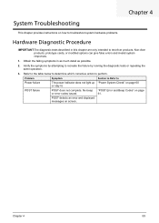
... Chapter 4 System Troubleshooting This chapter provides instructions on how to troubleshoot system hardware problems. Hardware Diagnostic Procedure IMPORTANT:The diagnostic tests described in as much detail as possible. 2. Problem Symptom Section to Refer to test Acer products. Chapter 4 59 POST failure POST does not complete. Obtain the failing ... on page 60 or stay lit. POST detects an error and displayed messages on page or error codes issued. 61. Non-Acer products, prototype cards, or modified options can give false errors and invalid system responses. 1.
... Chapter 4 System Troubleshooting This chapter provides instructions on how to troubleshoot system hardware problems. Hardware Diagnostic Procedure IMPORTANT:The diagnostic tests described in as much detail as possible. 2. Problem Symptom Section to Refer to test Acer products. Chapter 4 59 POST failure POST does not complete. Obtain the failing ... on page 60 or stay lit. POST detects an error and displayed messages on page or error codes issued. 61. Non-Acer products, prototype cards, or modified options can give false errors and invalid system responses. 1.
Aspire X1200 / X3200 Service Guide
Page 68
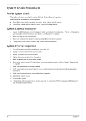
... 4. Remove the system covers. Verify that all cable connectors inside the system are properly seated. 8. Verify that all components are Acer-qualified and supported. 10. T Check if the voltage selector switch is properly connected to the correct voltage setting. Refer to "System... the system is not blocked. 3. System External Inspection 1. For instructions on removing system covers, refer to System External Inspection. If the problem is making contact that could short out power. 4. Unplug the power cord from the power outlets. 3. Replace the system covers. 11...
... 4. Remove the system covers. Verify that all cable connectors inside the system are properly seated. 8. Verify that all components are Acer-qualified and supported. 10. T Check if the voltage selector switch is properly connected to the correct voltage setting. Refer to "System... the system is not blocked. 3. System External Inspection 1. For instructions on removing system covers, refer to System External Inspection. If the problem is making contact that could short out power. 4. Unplug the power cord from the power outlets. 3. Replace the system covers. 11...
Aspire X1200 / X3200 Service Guide
Page 69
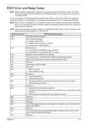
... Codes NOTE: Perform the FRU replacement or actions in the sequence shown in FRU/Action column, if the FRU replacement does not solve the problem, put the original part back in physical address 1000:0 Reserved Initial Superio_Earl_Init switch Reserved 1 Blank out screen 2 Clear CMOS error flag Reserved ... 04h 05h 06h 07h 08h 09h 0Ah 0Bh 0Ch 0Dh 0Eh 0Fh 10h 11h POST Routine Description Test CMOS R/W functionality Early chipset initialization T Disable shadow RAM T Disable L2 cache (socket 7 or below) T Program basic chipset registers Detect memory T Auto-detection of DRAM size, type, and ECC T...
... Codes NOTE: Perform the FRU replacement or actions in the sequence shown in FRU/Action column, if the FRU replacement does not solve the problem, put the original part back in physical address 1000:0 Reserved Initial Superio_Earl_Init switch Reserved 1 Blank out screen 2 Clear CMOS error flag Reserved ... 04h 05h 06h 07h 08h 09h 0Ah 0Bh 0Ch 0Dh 0Eh 0Fh 10h 11h POST Routine Description Test CMOS R/W functionality Early chipset initialization T Disable shadow RAM T Disable L2 cache (socket 7 or below) T Program basic chipset registers Detect memory T Auto-detection of DRAM size, type, and ECC T...


