
User Manual
Page 3
... and comfort Safety instructions Read these instructions carefully. The overall system load must not be seriously damaged. • Slots and openings are not sure of the type of any kind into this product, make sure that could be blocked or covered. If the product falls, it could result in too many devices. Follow all products plugged into the product...
... and comfort Safety instructions Read these instructions carefully. The overall system load must not be seriously damaged. • Slots and openings are not sure of the type of any kind into this product, make sure that could be blocked or covered. If the product falls, it could result in too many devices. Follow all products plugged into the product...
User Manual
Page 4
... devices that the new power cord meets the following the operating instructions Note: Adjust only those controls that are used, the load should not exceed 80% of this product from unexpected noise produced by a qualified technician to restore the product to replace the power cord set . Contact your electrician for service • the product does not operate normally after following requirements: detachable type, UL listed...
... devices that the new power cord meets the following the operating instructions Note: Adjust only those controls that are used, the load should not exceed 80% of this product from unexpected noise produced by a qualified technician to restore the product to replace the power cord set . Contact your electrician for service • the product does not operate normally after following requirements: detachable type, UL listed...
User Manual
Page 5
... LCD/CRT monitor or display: Lamp(s) inside this electronic device into the trash when discarding. For lamp-specific disposal information, check www.lamprecycle.org. v CAUTION: Danger of the global environment, please recycle. Telephone line safety • Disconnect all telephone lines from the equipment when not in use and/or before servicing. • To avoid the remote risk of...
... LCD/CRT monitor or display: Lamp(s) inside this electronic device into the trash when discarding. For lamp-specific disposal information, check www.lamprecycle.org. v CAUTION: Danger of the global environment, please recycle. Telephone line safety • Disconnect all telephone lines from the equipment when not in use and/or before servicing. • To avoid the remote risk of...

User Manual
Page 6
... of inactivity respectively. • Wake the computer from sleep mode by pushing keyboard or moving mouse. • Computers will save more than 80% energy at risk of physical injury after prolonged use. marks Tips and information for comfortable use less energy and prevent greenhouse gas emissions by meeting strict energy efficiency guidelines set by reducing energy cost and...
... of inactivity respectively. • Wake the computer from sleep mode by pushing keyboard or moving mouse. • Computers will save more than 80% energy at risk of physical injury after prolonged use. marks Tips and information for comfortable use less energy and prevent greenhouse gas emissions by meeting strict energy efficiency guidelines set by reducing energy cost and...

User Manual
Page 7
... strain Taking care of the monitor, using a footrest, or raising your company's health and safety department. Observe the following sections provide suggestions on your leg muscles • take short rests to relax your neck and shoulders • avoid tensing your muscles or shrugging your shoulders • install the external display, keyboard and mouse properly and within comfortable...
... strain Taking care of the monitor, using a footrest, or raising your company's health and safety department. Observe the following sections provide suggestions on your leg muscles • take short rests to relax your neck and shoulders • avoid tensing your muscles or shrugging your shoulders • install the external display, keyboard and mouse properly and within comfortable...
User Manual
Page 9
... optical discs 4 2 Setting up your computer 5 Arranging a comfortable work area 6 Positioning your monitor 6 Positioning your keyboard 6 Positioning your mouse 6 Connecting peripherals 7 Connecting your mouse and keyboard 7 USB interface 7 PS/2 interface 7 Connecting a monitor 7 Connecting the power cable 8 Turning on your computer 8 Turning off your computer 8 3 Upgrading your computer 9 Installation precautions 10 ESD precautions 10 Preinstallation instructions 10 Post-installation instructions 10 Opening your computer 11 To remove the computer cover...
... optical discs 4 2 Setting up your computer 5 Arranging a comfortable work area 6 Positioning your monitor 6 Positioning your keyboard 6 Positioning your mouse 6 Connecting peripherals 7 Connecting your mouse and keyboard 7 USB interface 7 PS/2 interface 7 Connecting a monitor 7 Connecting the power cable 8 Turning on your computer 8 Turning off your computer 8 3 Upgrading your computer 9 Installation precautions 10 ESD precautions 10 Preinstallation instructions 10 Post-installation instructions 10 Opening your computer 11 To remove the computer cover...
User Manual
Page 12
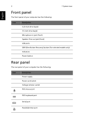
English 2 1 System tour Front panel The front panel of your computer has the following: Icon Description 5.25-inch drive bay(s) 3.5-inch drive bay(s) Microphone-in jack (front) Speaker-/line-out jack (front) USB ports OBR (One Button Recovery) button (For selected models only) Indicators Power button Rear panel The rear panel of your computer has the following: Icon Description Power supply Power cord socket Voltage selector switch PS/2 mouse port PS/2 keyboard port Serial port Parallel/printer port
English 2 1 System tour Front panel The front panel of your computer has the following: Icon Description 5.25-inch drive bay(s) 3.5-inch drive bay(s) Microphone-in jack (front) Speaker-/line-out jack (front) USB ports OBR (One Button Recovery) button (For selected models only) Indicators Power button Rear panel The rear panel of your computer has the following: Icon Description Power supply Power cord socket Voltage selector switch PS/2 mouse port PS/2 keyboard port Serial port Parallel/printer port
User Manual
Page 13
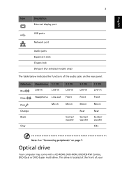
... Description External display port USB ports Network port Audio jacks Expansion slots Chassis lock DVI port (for selected models only) The table below indicates the functions of your This drive is located at the front of the audio jacks on the rear panel: Color/use Blue Green Pink Orange Black Gray Headphone 1.1 CH Line-in Line-in Headphone Line-out Mic-in 3.1 CH Line-in Front Mic-in Center...
... Description External display port USB ports Network port Audio jacks Expansion slots Chassis lock DVI port (for selected models only) The table below indicates the functions of your This drive is located at the front of the audio jacks on the rear panel: Color/use Blue Green Pink Orange Black Gray Headphone 1.1 CH Line-in Line-in Headphone Line-out Mic-in 3.1 CH Line-in Front Mic-in Center...
User Manual
Page 14
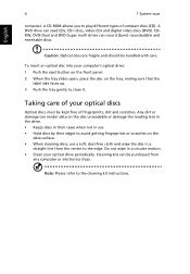
CDRW, DVD-Dual and DVD-Super multi drives can read CDs, CD-I discs, video-CDs and digital video discs (DVD). Taking care of your computer's optical drive: 1 Push the eject button on the front panel. 2 When the tray slides open, place the disc on the tray, maling sure that the label side faces up. 3 Push the tray gently to close it. A DVD drive can record (burn) recordadable and...
CDRW, DVD-Dual and DVD-Super multi drives can read CDs, CD-I discs, video-CDs and digital video discs (DVD). Taking care of your computer's optical drive: 1 Push the eject button on the front panel. 2 When the tray slides open, place the disc on the tray, maling sure that the label side faces up. 3 Push the tray gently to close it. A DVD drive can record (burn) recordadable and...
User Manual
Page 16
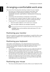
... to the floor as your keyboard so that Positioning your keyboard The location of the keyboard is at a comfortable viewing distance, usually 50 to your lap. Putting your keyboard beside your monitor will make your PC in the upright position. Positioning your mouse • The mouse should be relaxed. English 6 2 Setting up your computer Arranging a comfortable work area Take note of...
... to the floor as your keyboard so that Positioning your keyboard The location of the keyboard is at a comfortable viewing distance, usually 50 to your lap. Putting your keyboard beside your monitor will make your PC in the upright position. Positioning your mouse • The mouse should be relaxed. English 6 2 Setting up your computer Arranging a comfortable work area Take note of...
User Manual
Page 17
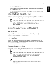
... most part, you stretch or lean over. • Use your wrist on the table when moving the mouse. Actual device models may vary in the connections below are for your computer is added to the PCI Express slot, the monitor should be connected to the add-on card and the onboard VGA will be disabled. located PS/2 interface Plug the PS/2 keyboard cable into the monitor (blue) port on the rear panel of...
... most part, you stretch or lean over. • Use your wrist on the table when moving the mouse. Actual device models may vary in the connections below are for your computer is added to the PCI Express slot, the monitor should be connected to the add-on card and the onboard VGA will be disabled. located PS/2 interface Plug the PS/2 keyboard cable into the monitor (blue) port on the rear panel of...
User Manual
Page 18
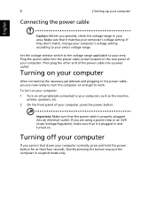
..., change your computer's voltage setting according to your area. Turning on your computer After connecting the necessary peripherals and plugging in and turned on all peripherals connected to work. Quickly pressing the button may put the computer in your computer: 1 Turn on . Make sure that the power cable is plugged in the power cable, you are now ready to turn on your area. Plug the power cable into the power cable socket located...
..., change your computer's voltage setting according to your area. Turning on your computer After connecting the necessary peripherals and plugging in and turned on all peripherals connected to work. Quickly pressing the button may put the computer in your computer: 1 Turn on . Make sure that the power cable is plugged in the power cable, you are now ready to turn on your area. Plug the power cable into the power cable socket located...
User Manual
Page 20
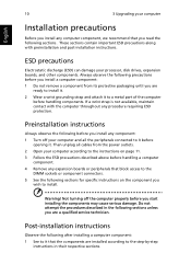
... wish to the step-by-step instructions in the following sections for specific instructions on page 11. 3 Follow the ESD precautions described above before handling a computer component. 4 Remove any component: 1 Turn off the computer properly before opening it before you install a computer component: 1 Do not remove a component from the power outlets. 2 Open your processor, disk drives, expansion boards, and other components. Always observe the...
... wish to the step-by-step instructions in the following sections for specific instructions on page 11. 3 Follow the ESD precautions described above before handling a computer component. 4 Remove any component: 1 Turn off the computer properly before opening it before you install a computer component: 1 Do not remove a component from the power outlets. 2 Open your processor, disk drives, expansion boards, and other components. Always observe the...
User Manual
Page 21
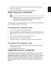
... instructions. To replace the computer cover 1 Align the cover's hinges to replace or upgrade any expansion boards or peripherals that you have turned off your computer and unplug all peripherals connected to detach it . However, for safety purposes, we do not recommend that you removed earlier. 3 Replace the side panels. 4 Connect the necessary cables and turn on your computer. Opening your computer Caution: Before you proceed, make...
... instructions. To replace the computer cover 1 Align the cover's hinges to replace or upgrade any expansion boards or peripherals that you have turned off your computer and unplug all peripherals connected to detach it . However, for safety purposes, we do not recommend that you removed earlier. 3 Replace the side panels. 4 Connect the necessary cables and turn on your computer. Opening your computer Caution: Before you proceed, make...
User Manual
Page 23
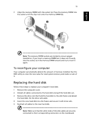
...'s hard disk: 1 Remove the computer cover. 2 Detach all cables to the new hard disk. Note: Make sure that hold the hard disk to the disk frame and detach the hard disk. Run the BIOS utility to view the new value for total system memory and make a note of it again. If you insert a memory DIMM but it does not fit easily into the frame and secure it with the socket (a). Set the drive...
...'s hard disk: 1 Remove the computer cover. 2 Detach all cables to the new hard disk. Note: Make sure that hold the hard disk to the disk frame and detach the hard disk. Run the BIOS utility to view the new value for total system memory and make a note of it again. If you insert a memory DIMM but it does not fit easily into the frame and secure it with the socket (a). Set the drive...
User Manual
Page 24
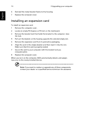
... replace or upgrade any of these components, contact your computer 6 Reinstall the metal bracket frame to the newly installed devices. Save the lock. 4 Pull out the bracket on the computer, BIOS automatically detects and assigns resources to the housing. 7 Replace the computer cover. When you removed earlier. 8 Replace the computer cover. Installing an expansion card To install an expansion card: 1 Remove the computer cover. 2 Locate an empty PCI...
... replace or upgrade any of these components, contact your computer 6 Reinstall the metal bracket frame to the newly installed devices. Save the lock. 4 Pull out the bracket on the computer, BIOS automatically detects and assigns resources to the housing. 7 Replace the computer cover. When you removed earlier. 8 Replace the computer cover. Installing an expansion card To install an expansion card: 1 Remove the computer cover. 2 Locate an empty PCI...
User Manual
Page 26
... the printer cable is plugged in a drive? Just press any key to save power. The printer does not work , you are using a power strip, make sure it is followed by easy answers and solutions. If the LED is correctly attached to restart your dealer or technical support center for the Volume icon on . Your computer's power management function automatically blanks the screen to turn the display back on...
... the printer cable is plugged in a drive? Just press any key to save power. The printer does not work , you are using a power strip, make sure it is followed by easy answers and solutions. If the LED is correctly attached to restart your dealer or technical support center for the Volume icon on . Your computer's power management function automatically blanks the screen to turn the display back on...
User Manual
Page 27
... are using a good (undamaged) disk. If your drive by using the correct type of disc. System cannot write data on the good disk there may be a problem with the drive. English 17 press the volume control/mute knob on your USB keyboard to toggle from mute to sound on. • If headphones, earphones or external speakers are connected to the lineout jack of your dealer or technical support center...
... are using a good (undamaged) disk. If your drive by using the correct type of disc. System cannot write data on the good disk there may be a problem with the drive. English 17 press the volume control/mute knob on your USB keyboard to toggle from mute to sound on. • If headphones, earphones or external speakers are connected to the lineout jack of your dealer or technical support center...
User Manual
Page 32
... network services. 2 This equipment is causing the problem. TBR 21 This equipment has been approved [Council Decision 98/482/EC - However, due to determine if it provide any single manual call attempts to the same number within the following limits for single terminal connection to operate ...Telecom has accepted that any product is compatible with Telecom's Specifications: a There shall be set to the Public Switched Telephone Network (PSTN). It indicates no assurance that any item of correct operation at the higher speeds for which it imply that the item complies with a ...
... network services. 2 This equipment is causing the problem. TBR 21 This equipment has been approved [Council Decision 98/482/EC - However, due to determine if it provide any single manual call attempts to the same number within the following limits for single terminal connection to operate ...Telecom has accepted that any product is compatible with Telecom's Specifications: a There shall be set to the Public Switched Telephone Network (PSTN). It indicates no assurance that any item of correct operation at the higher speeds for which it imply that the item complies with a ...

User Manual
Page 33
... WHEN OPEN. There is DTMF tone dialing. This has no guarantee that Telecom lines will always continue to support pulse dialing. 7 Use of another device connected to the same line. 9 Under power failure conditions this appliance may not operate. Laser compliance statement The CD or DVD drive used with this computer is produced with Telecom's specifications, the associated equipment shall be set to...
... WHEN OPEN. There is DTMF tone dialing. This has no guarantee that Telecom lines will always continue to support pulse dialing. 7 Use of another device connected to the same line. 9 Under power failure conditions this appliance may not operate. Laser compliance statement The CD or DVD drive used with this computer is produced with Telecom's specifications, the associated equipment shall be set to...


