User Manual
Page 2
Copyright © 2009. All Rights Reserved. AcerSystem User Guide Original Issue: 04 / 2009 AcerSystem Desktop Computer Model number Serial number Purchase date Place of purchase Visit registration.acer.com and discover the benefits of being an Acer customer.
Copyright © 2009. All Rights Reserved. AcerSystem User Guide Original Issue: 04 / 2009 AcerSystem Desktop Computer Model number Serial number Purchase date Place of purchase Visit registration.acer.com and discover the benefits of being an Acer customer.

User Manual
Page 3
The openings should never be blocked by plugging in too many devices. Do not locate this product where people will walk on the cord. • If an extension cord is provided. • Never push objects of any kind onto or into the extension cord does not exceed the extension cord ampere rating. Follow all products plugged into this document for your dealer or local power company. • Do not allow anything to rest on the marking label. Warnings • Do not use liquid cleaners or aerosol cleaners. If you are provided for cleaning. Keep this product through cabinet ...
The openings should never be blocked by plugging in too many devices. Do not locate this product where people will walk on the cord. • If an extension cord is provided. • Never push objects of any kind onto or into the extension cord does not exceed the extension cord ampere rating. Follow all products plugged into this document for your dealer or local power company. • Do not allow anything to rest on the marking label. Warnings • Do not use liquid cleaners or aerosol cleaners. If you are provided for cleaning. Keep this product through cabinet ...
User Manual
Page 4
If power strips are covered by the operating instructions, since improper adjustment of other controls may result in a grounded power outlet. Using a power outlet that is not properly grounded may result in damage and will often require extensive work by other risks. Refer all servicing to rain or water • the product has been dropped or the case has been damaged • the product exhibits a distinct change in performance, indicating a need to replace the power cord set . iv circuit rating. Do not insert the plug into the product • the product was spilled into a non...
If power strips are covered by the operating instructions, since improper adjustment of other controls may result in a grounded power outlet. Using a power outlet that is not properly grounded may result in damage and will often require extensive work by other risks. Refer all servicing to rain or water • the product has been dropped or the case has been damaged • the product exhibits a distinct change in performance, indicating a need to replace the power cord set . iv circuit rating. Do not insert the plug into the product • the product was spilled into a non...
User Manual
Page 5
... not in use and/or before servicing. • To avoid the remote risk of electric shock from Electrical and Electronics Equipment (WEEE) regulations, visit www.acer-group.com/public/Sustainability/sustainability01.htm. For more information on the Waste from lightning, do not connect the telephone line to local, state or federal...
... not in use and/or before servicing. • To avoid the remote risk of electric shock from Electrical and Electronics Equipment (WEEE) regulations, visit www.acer-group.com/public/Sustainability/sustainability01.htm. For more information on the Waste from lightning, do not connect the telephone line to local, state or federal...

User Manual
Page 6
...guidelines set by reducing energy cost and protecting the environment without sacrificing features or performance. Incorrect computer usage may lead to Acer system with the ENERGY STAR mark. marks Tips and information for comfortable use Computer users may appear in front of working... greatly increase the risk of physical injury. Products that help customers save money, conserve energy and improve the quality of climate change. Acer ENERGY STAR qualified products: • Produce less heat and reduce cooling loads, and warmer climates. • Automatically go into "display...
...guidelines set by reducing energy cost and protecting the environment without sacrificing features or performance. Incorrect computer usage may lead to Acer system with the ENERGY STAR mark. marks Tips and information for comfortable use Computer users may appear in front of working... greatly increase the risk of physical injury. Products that help customers save money, conserve energy and improve the quality of climate change. Acer ENERGY STAR qualified products: • Produce less heat and reduce cooling loads, and warmer climates. • Automatically go into "display...

User Manual
Page 7
The following section provides tips for more than your documents, place the display at the center of your desk to minimize neck strain Taking care of the monitor, using a footrest, or raising your eyes. Observe the following sections provide suggestions on your leg muscles • take short rests to achieve maximum comfort. The following tips: • refrain from staying too long in one fixed posture • avoid slouching forward and/or leaning backward • stand up and walk around regularly to remove the strain on how to computer use . Finding your comfort zone Find ...
The following section provides tips for more than your documents, place the display at the center of your desk to minimize neck strain Taking care of the monitor, using a footrest, or raising your eyes. Observe the following sections provide suggestions on your leg muscles • take short rests to achieve maximum comfort. The following tips: • refrain from staying too long in one fixed posture • avoid slouching forward and/or leaning backward • stand up and walk around regularly to remove the strain on how to computer use . Finding your comfort zone Find ...
User Manual
Page 8
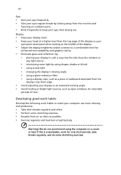
Display • Keep your display clean. • Keep your head at a higher level than the top edge of the display so your eyes point downward when looking at the middle of the display. • Adjust the display brightness and/or contrast to a comfortable level for enhanced text readability and graphics clarity. • Eliminate glare and reflections by: • placing your display in such a way that the side faces the window or any light source • minimizing room light by looking at bright light sources, such as open windows, for extended periods of cardboard extended from the ...
Display • Keep your display clean. • Keep your head at a higher level than the top edge of the display so your eyes point downward when looking at the middle of the display. • Adjust the display brightness and/or contrast to a comfortable level for enhanced text readability and graphics clarity. • Eliminate glare and reflections by: • placing your display in such a way that the side faces the window or any light source • minimizing room light by looking at bright light sources, such as open windows, for extended periods of cardboard extended from the ...
User Manual
Page 9
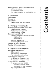
Contents Information for your safety and comfort iii Safety instructions iii Disposal instructions v Tips and information for comfortable use vi 1 System tour 1 Front panel 2 Rear panel 2 Optical drive 3 Taking care of your optical discs 4 2 Setting up your computer 5 Arranging a comfortable work area 6 Positioning your monitor 6 Positioning your keyboard 6 Positioning your mouse 6 Connecting peripherals 7 Connecting your mouse and keyboard 7 USB interface 7 PS/2 interface 7 Connecting a monitor 7 Connecting the power cable 8 Turning on your computer 8...
Contents Information for your safety and comfort iii Safety instructions iii Disposal instructions v Tips and information for comfortable use vi 1 System tour 1 Front panel 2 Rear panel 2 Optical drive 3 Taking care of your optical discs 4 2 Setting up your computer 5 Arranging a comfortable work area 6 Positioning your monitor 6 Positioning your keyboard 6 Positioning your mouse 6 Connecting peripherals 7 Connecting your mouse and keyboard 7 USB interface 7 PS/2 interface 7 Connecting a monitor 7 Connecting the power cable 8 Turning on your computer 8...
User Manual
Page 10
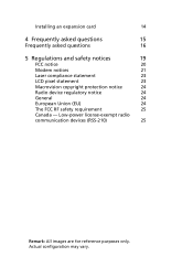
Actual configuration may vary. Installing an expansion card 14 4 Frequently asked questions 15 Frequently asked questions 16 5 Regulations and safety notices 19 FCC notice 20 Modem notices 21 Laser compliance statement 23 LCD pixel statement 23 Macrovision copyright protection notice 24 Radio device regulatory notice 24 General 24 European Union (EU) 24 The FCC RF safety requirement 25 Canada - Low-power license-exempt radio communication devices (RSS-210) 25 Remark: All images are for reference purposes only.
Actual configuration may vary. Installing an expansion card 14 4 Frequently asked questions 15 Frequently asked questions 16 5 Regulations and safety notices 19 FCC notice 20 Modem notices 21 Laser compliance statement 23 LCD pixel statement 23 Macrovision copyright protection notice 24 Radio device regulatory notice 24 General 24 European Union (EU) 24 The FCC RF safety requirement 25 Canada - Low-power license-exempt radio communication devices (RSS-210) 25 Remark: All images are for reference purposes only.
User Manual
Page 12
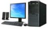
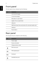
English 2 1 System tour Front panel The front panel of your computer has the following: Icon Description 5.25-inch drive bay(s) 3.5-inch drive bay(s) Microphone-in jack (front) Speaker-/line-out jack (front) USB ports OBR (One Button Recovery) button (For selected models only) Indicators Power button Rear panel The rear panel of your computer has the following: Icon Description Power supply Power cord socket Voltage selector switch PS/2 mouse port PS/2 keyboard port Serial port Parallel/printer port
English 2 1 System tour Front panel The front panel of your computer has the following: Icon Description 5.25-inch drive bay(s) 3.5-inch drive bay(s) Microphone-in jack (front) Speaker-/line-out jack (front) USB ports OBR (One Button Recovery) button (For selected models only) Indicators Power button Rear panel The rear panel of your computer has the following: Icon Description Power supply Power cord socket Voltage selector switch PS/2 mouse port PS/2 keyboard port Serial port Parallel/printer port
User Manual
Page 13
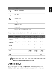
English 3 Icon Description External display port USB ports Network port Audio jacks Expansion slots Chassis lock DVI port (for selected models only) The table below indicates the functions of your This drive is located at the front of the audio jacks on the rear panel: Color/use Blue Green Pink Orange Black Gray Headphone 1.1 CH Line-in Line-in Headphone Line-out Mic-in 3.1 CH Line-in Front Mic-in Center/ woofer 5.1 CH Line-in Front Mic-in Rear Center/ woofer 7.1 CH Line-in Front Mic-in Rear Center/ woofer Side Note: See "Connecting peripherals" on page 7. Optical drive ...
English 3 Icon Description External display port USB ports Network port Audio jacks Expansion slots Chassis lock DVI port (for selected models only) The table below indicates the functions of your This drive is located at the front of the audio jacks on the rear panel: Color/use Blue Green Pink Orange Black Gray Headphone 1.1 CH Line-in Line-in Headphone Line-out Mic-in 3.1 CH Line-in Front Mic-in Center/ woofer 5.1 CH Line-in Front Mic-in Rear Center/ woofer 7.1 CH Line-in Front Mic-in Rear Center/ woofer Side Note: See "Connecting peripherals" on page 7. Optical drive ...
User Manual
Page 14
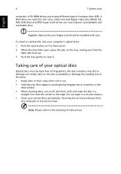
Note: Please refer to play different types of fingerprints, dirt and scratches. Cleaning kits can render data on the disc unreadable or damage the reading lens in the drive. • Keeps discs in their cases when not in use a soft, dust-free cloth and wipe the disc in a circular motion. • Clean your optical drive periodically. Taking care of your computer's optical drive: 1 Push the eject button on the front panel. 2 When the tray slides open, place the disc on the data surface. • When cleaning discs, use . • Hold discs by their edges to avoid getting...
Note: Please refer to play different types of fingerprints, dirt and scratches. Cleaning kits can render data on the disc unreadable or damage the reading lens in the drive. • Keeps discs in their cases when not in use a soft, dust-free cloth and wipe the disc in a circular motion. • Clean your optical drive periodically. Taking care of your computer's optical drive: 1 Push the eject button on the front panel. 2 When the tray slides open, place the disc on the data surface. • When cleaning discs, use . • Hold discs by their edges to avoid getting...

User Manual
Page 15
2 Setting up your computer
2 Setting up your computer
User Manual
Page 16
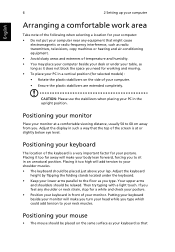
Positioning your keyboard The location of your monitor. Positioning your monitor Place your monitor at or slightly below eye level. Adjust the keyboard height by flipping the folding stands located under your table, as long as it does not block the space you need for working and moving. • To place your PC in a vertical position (for selected models) : • Rotate the plastic stabilizers on the same surface as your keyboard so that Placing it too far away will make you turn your head while you type which could add tension to your neck muscles. Your upper arms and ...
Positioning your keyboard The location of your monitor. Positioning your monitor Place your monitor at or slightly below eye level. Adjust the keyboard height by flipping the folding stands located under your table, as long as it does not block the space you need for working and moving. • To place your PC in a vertical position (for selected models) : • Rotate the plastic stabilizers on the same surface as your keyboard so that Placing it too far away will make you turn your head while you type which could add tension to your neck muscles. Your upper arms and ...
User Manual
Page 17
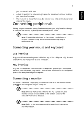
English 7 you can reach it with ease. • Adjust its position to allow enough space for movement without making you only have four things to move the mouse. Connecting peripherals Setting up your wrist on the rear panel of your computer. For the most part, you stretch or lean over. • Use your arm to connect: the mouse, keyboard, monitor and power cable. Actual device models may vary in the connections below are for additional instructions and information. Connecting your mouse and keyboard USB interface Plug your USB mouse or keyboard cable into the PS/2 mouse (...
English 7 you can reach it with ease. • Adjust its position to allow enough space for movement without making you only have four things to move the mouse. Connecting peripherals Setting up your wrist on the rear panel of your computer. For the most part, you stretch or lean over. • Use your arm to connect: the mouse, keyboard, monitor and power cable. Actual device models may vary in the connections below are for additional instructions and information. Connecting your mouse and keyboard USB interface Plug your USB mouse or keyboard cable into the PS/2 mouse (...
User Manual
Page 18
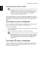
Set the voltage selector switch to the voltage range applicable to your area's voltage range. Then plug the other end of your computer, press the power button. If you cannot shut down your computer normally, press and hold the power button for at least four seconds. Turning on your computer After connecting the necessary peripherals and plugging in the power cable, you proceed, check the voltage range in your area. To turn the computer on and get to work. Plug the power cable into an electrical outlet. Make sure that it matches your computer's voltage setting. Important: ...
Set the voltage selector switch to the voltage range applicable to your area's voltage range. Then plug the other end of your computer, press the power button. If you cannot shut down your computer normally, press and hold the power button for at least four seconds. Turning on your computer After connecting the necessary peripherals and plugging in the power cable, you proceed, check the voltage range in your area. To turn the computer on and get to work. Plug the power cable into an electrical outlet. Make sure that it matches your computer's voltage setting. Important: ...

User Manual
Page 19
3 Upgrading your computer
3 Upgrading your computer
User Manual
Page 20
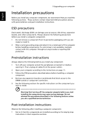
Preinstallation instructions Always observe the following before you install any expansion boards or peripherals that block access to the DIMM sockets or component connectors. 5 See the following sections for specific instructions on page 11. 3 Follow the ESD precautions described above before opening it that you wish to the step-by-step instructions in the following sections unless you start installing the components may cause serious damage. Then unplug all the peripherals connected to it before handling a computer component. 4 Remove any component: 1 Turn off the computer ...
Preinstallation instructions Always observe the following before you install any expansion boards or peripherals that block access to the DIMM sockets or component connectors. 5 See the following sections for specific instructions on page 11. 3 Follow the ESD precautions described above before opening it that you wish to the step-by-step instructions in the following sections unless you start installing the components may cause serious damage. Then unplug all the peripherals connected to it before handling a computer component. 4 Remove any component: 1 Turn off the computer ...
User Manual
Page 21
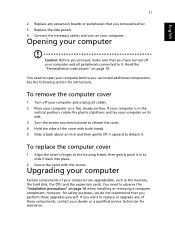
See the following section for safety purposes, we do not recommend that you can install additional components. To remove the computer cover 1 Turn off your computer before you perform these components, contact your dealer or a qualified service technician for assistance. To replace the computer cover 1 Align the cover's hinges to slide it back into place. 2 Secure the cover with both hands. 5 Slide it back about an inch and then gently lift it upward to observe the "Installation precautions" on page 10. English 11 2 Replace any of the cover with the screws. Upgrading your ...
See the following section for safety purposes, we do not recommend that you can install additional components. To remove the computer cover 1 Turn off your computer before you perform these components, contact your dealer or a qualified service technician for assistance. To replace the computer cover 1 Align the cover's hinges to slide it back into place. 2 Secure the cover with both hands. 5 Slide it back about an inch and then gently lift it upward to observe the "Installation precautions" on page 10. English 11 2 Replace any of the cover with the screws. Upgrading your ...

User Manual
Page 22
To install a memory DIMM 1 Locate the memory DIMM socket on both sides of the memory DIMM socket outward to release the memory DIMM (a). Gently pull the memory DIMM out of the socket (b). English 12 3 Upgrading your computer To remove a memory DIMM Note: The memory DIMM has only one notch located toward the center of the module. 1 Remove the side panel. 2 Locate the memory DIMM socket on the mainboard. 3 Press the holding clips on the mainboard.
To install a memory DIMM 1 Locate the memory DIMM socket on both sides of the memory DIMM socket outward to release the memory DIMM (a). Gently pull the memory DIMM out of the socket (b). English 12 3 Upgrading your computer To remove a memory DIMM Note: The memory DIMM has only one notch located toward the center of the module. 1 Remove the side panel. 2 Locate the memory DIMM socket on the mainboard. 3 Press the holding clips on the mainboard.