
Veriton 5200
Page 8
... 49 To replace the computer cover 50 Internal components 51 System boards 52 Mainboard layout 52 Audio board 55 Upgrading your computer 56 Installing additional memory 56 Replacing the hard disk 58 Installing an expansion card 60 5 System utilities 63 System utilities 65 Acrobat Reader 65 LANDesk Client Manager (LDCM) 65...
... 49 To replace the computer cover 50 Internal components 51 System boards 52 Mainboard layout 52 Audio board 55 Upgrading your computer 56 Installing additional memory 56 Replacing the hard disk 58 Installing an expansion card 60 5 System utilities 63 System utilities 65 Acrobat Reader 65 LANDesk Client Manager (LDCM) 65...
Veriton 5200
Page 17
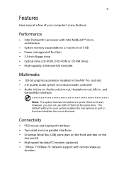
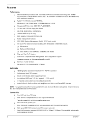
... on the rear panel) • High-speed fax/data PCI modem (optional) • 10Base-T/100Base-TX network support with Intel NetBurst™ microarchitecture • System memory expandable to a maximum of them at the back.
... on the rear panel) • High-speed fax/data PCI modem (optional) • 10Base-T/100Base-TX network support with Intel NetBurst™ microarchitecture • System memory expandable to a maximum of them at the back.
Veriton 5200
Page 61
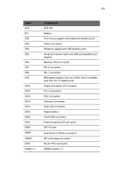
... PS/2 mouse (upper) and keyboard (lower) ports Power connector Network (upper) and USB (lower) ports Serial port (lower right and left) and parallel port (upper) Memory stick connector IDE 2 connector IDE 1 connector MIDI/game (upper), line-out (left), line-in (middle), and rear mic-in (right) ports Power connector (12 V power...
... PS/2 mouse (upper) and keyboard (lower) ports Power connector Network (upper) and USB (lower) ports Serial port (lower right and left) and parallel port (upper) Memory stick connector IDE 2 connector IDE 1 connector MIDI/game (upper), line-out (left), line-in (middle), and rear mic-in (right) ports Power connector (12 V power...
Veriton 5200
Page 64
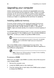
...remove a DIMM Before you to install DIMMs with different capacities to release the DIMM (a). The SDRAM DIMMs should work under 3.3 volts; 5-volt memory devices are supported. Such a combination might cause your dealer or a qualified service technician for assistance. Note: Observe the "ESD precautions" on both... 3 Press the holding clips on page 47 when installing or removing a computer component. Contact your computer are upgradeable such as the memory, the hard disk and the expansion cards. Caution: Do not install and use both sides of the DIMM socket outward to form ...
...remove a DIMM Before you to install DIMMs with different capacities to release the DIMM (a). The SDRAM DIMMs should work under 3.3 volts; 5-volt memory devices are supported. Such a combination might cause your dealer or a qualified service technician for assistance. Note: Observe the "ESD precautions" on both... 3 Press the holding clips on page 47 when installing or removing a computer component. Contact your computer are upgradeable such as the memory, the hard disk and the expansion cards. Caution: Do not install and use both sides of the DIMM socket outward to form ...
Veriton 5200
Page 66
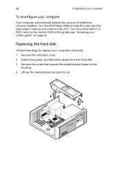
...Lift up the metal bracket and pull it . Replacing the hard disk Follow these steps to replace your online guide" on BIOS, refer to the Veriton 5200 online guide (see "Accessing your computer's hard disk: 1 Remove the computer cover. 2 Detach the power and disk drive cables from the hard ...disk. 3 Remove the screw that secures the metal bracket frame to view the new value for total system memory and make a note of additional memory installed. For more information on page 5). 58 4 Upgrading your computer To reconfigure your computer Your computer automatically detects the...
...Lift up the metal bracket and pull it . Replacing the hard disk Follow these steps to replace your online guide" on BIOS, refer to the Veriton 5200 online guide (see "Accessing your computer's hard disk: 1 Remove the computer cover. 2 Detach the power and disk drive cables from the hard ...disk. 3 Remove the screw that secures the metal bracket frame to view the new value for total system memory and make a note of additional memory installed. For more information on page 5). 58 4 Upgrading your computer To reconfigure your computer Your computer automatically detects the...
Veriton 5200
Page 85
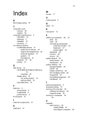
... programs 69 VariSpeed 67 T technical assistance 5 troubleshooting 73 turning off computer 36 software shutdown 36 suspend mode 36 turning on computer 34 34 U upgrade add memory 56 install DIMM 57 reconfigure computer 58
... programs 69 VariSpeed 67 T technical assistance 5 troubleshooting 73 turning off computer 36 software shutdown 36 suspend mode 36 turning on computer 34 34 U upgrade add memory 56 install DIMM 57 reconfigure computer 58

Veriton 5200 Service Guide
Page 5
... web or channel. To better fit local market requirements and enhance product competitiveness, your Acer office may have decided to -date information available on card, modem, or extra memory capability). V Please note WHEN ORDERING FRU PARTS, that you should check the most ...with further technical details. 2. These LOCALIZED FEATURES will not be covered in the printed Service Guide. If, for Acer's "global" product offering. For ACER-AUTHORIZED SERVICE PROVIDERS, your regional office MAY have a DIFFERENT part number code to the BASIC CONFIGURATION decided for whatever ...
... web or channel. To better fit local market requirements and enhance product competitiveness, your Acer office may have decided to -date information available on card, modem, or extra memory capability). V Please note WHEN ORDERING FRU PARTS, that you should check the most ...with further technical details. 2. These LOCALIZED FEATURES will not be covered in the printed Service Guide. If, for Acer's "global" product offering. For ACER-AUTHORIZED SERVICE PROVIDERS, your regional office MAY have a DIFFERENT part number code to the BASIC CONFIGURATION decided for whatever ...
Veriton 5200 Service Guide
Page 11
Hardware monitor function ! One microphone jack and one speaker jack on -die L2 cache memory in 82801BA chipset). ! Two high-speed NS 16C550-compatible serial ports ! One RJ45 connector supports IEEE 802./802.3u 10Base-T/100Base-TX-compatible network with ...
Hardware monitor function ! One microphone jack and one speaker jack on -die L2 cache memory in 82801BA chipset). ! Two high-speed NS 16C550-compatible serial ports ! One RJ45 connector supports IEEE 802./802.3u 10Base-T/100Base-TX-compatible network with ...
Veriton 5200 Service Guide
Page 12
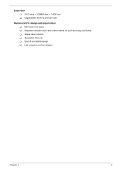
Separate computer stand and rubber stands for quick and easy positioning ! Accessible I/O ports ! Space-saver solution ! Low emission and low radiation Chapter 1 3 Mini-tower form factor ! Smooth and stylish design ! Expansion ! 3 PCI slots + 3 DIMM slots + 1 AGP slot ! Upgradeable memory and hard disk Human-centric design and ergonomics !
Separate computer stand and rubber stands for quick and easy positioning ! Accessible I/O ports ! Space-saver solution ! Low emission and low radiation Chapter 1 3 Mini-tower form factor ! Smooth and stylish design ! Expansion ! 3 PCI slots + 3 DIMM slots + 1 AGP slot ! Upgradeable memory and hard disk Human-centric design and ergonomics !
Veriton 5200 Service Guide
Page 19
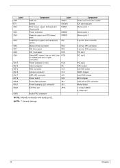
... keyboard (lower) ports DIMM1 Power connector DIMM2 Network (upper) and USB (lower) ports DIMM3 Parallel port (upper) and serial ports FN1 (lower ) Memory Stick Connector FN2 IDE 2 connector FN3 IDE 1 connector PCI1 Game/MIDI (upper), line-out (left), line- PCI2 in (middle) and mic-in ...Audio FPIO connector NOTE: Shared connection with serial port 2, NOTE: ** Default Settings Component Smart card connector (com2)* IDE cold swap pin Memory slot 1 Memory slot 2 Memory slot 3 3-pin fan SYS connector 3-pin fan CPU connector 3-pin fan SYS connector PCI slot 1 PCI slot 2 PCI slot 3 CPU...
... keyboard (lower) ports DIMM1 Power connector DIMM2 Network (upper) and USB (lower) ports DIMM3 Parallel port (upper) and serial ports FN1 (lower ) Memory Stick Connector FN2 IDE 2 connector FN3 IDE 1 connector PCI1 Game/MIDI (upper), line-out (left), line- PCI2 in (middle) and mic-in ...Audio FPIO connector NOTE: Shared connection with serial port 2, NOTE: ** Default Settings Component Smart card connector (com2)* IDE cold swap pin Memory slot 1 Memory slot 2 Memory slot 3 3-pin fan SYS connector 3-pin fan CPU connector 3-pin fan SYS connector PCI slot 1 PCI slot 2 PCI slot 3 CPU...
Veriton 5200 Service Guide
Page 22
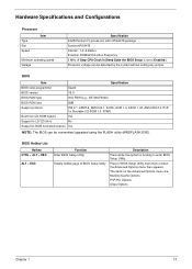
... boot block feature Yes NOTE: The BIOS can be overwritten/upgraded using the FLASH utility (AWDFLASH.EXE). The items on the Advanced Options menu are: Memory/Cache Options PnP/PCI Options Chips Options Chapter 1 13 Hardware Specifications and Configurations Processor Type Slot Speed Item Minimum operating speed Voltage Specification Intel®...
... boot block feature Yes NOTE: The BIOS can be overwritten/upgraded using the FLASH utility (AWDFLASH.EXE). The items on the Advanced Options menu are: Memory/Cache Options PnP/PCI Options Chips Options Chapter 1 13 Hardware Specifications and Configurations Processor Type Slot Speed Item Minimum operating speed Voltage Specification Intel®...
Veriton 5200 Service Guide
Page 23
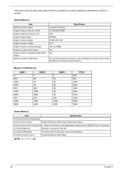
...) 3.3V 168 -pin DIMM Yes Yes Specification You can install memory modules in any combination as long as they match the Memory Combination specifications. System Memory Item Memory socket number Support memory size per socket Support maximum memory size Support memory type Support memory speed Support memory voltage Support memory module package Support to parity check feature Support to system...
...) 3.3V 168 -pin DIMM Yes Yes Specification You can install memory modules in any combination as long as they match the Memory Combination specifications. System Memory Item Memory socket number Support memory size per socket Support maximum memory size Support memory type Support memory speed Support memory voltage Support memory module package Support to parity check feature Support to system...
Veriton 5200 Service Guide
Page 26
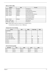
.... UPPER LIMIT UPPER LIMIT - 4GBytes 64KBytes Function Host Memory Host/PCI Memory PCI/ISA Video Buffer Memory Video BIOS Memory ISA Card BIOS & Buffer Memory BIOS Extension Memory Setup and Post Memory PCI Development BIOS System BIOS Memory Main Memory PCI Memory Note : UPPER LIMIT means the maximum size of installed memory. Mask 68h FFh 61h FFh 60h FFh 61h FFh...
.... UPPER LIMIT UPPER LIMIT - 4GBytes 64KBytes Function Host Memory Host/PCI Memory PCI/ISA Video Buffer Memory Video BIOS Memory ISA Card BIOS & Buffer Memory BIOS Extension Memory Setup and Post Memory PCI Development BIOS System BIOS Memory Main Memory PCI Memory Note : UPPER LIMIT means the maximum size of installed memory. Mask 68h FFh 61h FFh 60h FFh 61h FFh...
Veriton 5200 Service Guide
Page 30
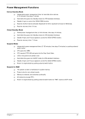
... Mode ! Global power management timer (2-120 minutes, time step=10 minute). ! Independent power management timer for Windows). ! Hard disk drive goes into SMM. ! Chapter 1 21 Memory is maintained in system memory ! Hard disk drive goes into Standby mode (for ATA standard interface). !
... Mode ! Global power management timer (2-120 minutes, time step=10 minute). ! Independent power management timer for Windows). ! Hard disk drive goes into SMM. ! Chapter 1 21 Memory is maintained in system memory ! Hard disk drive goes into Standby mode (for ATA standard interface). !
Veriton 5200 Service Guide
Page 31
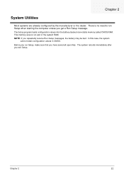
... files. In this case, the system cannot retain configuration values in CMOS. Before you run Setup when starting the computer unless you exit Setup. This memory area is no need to run Setup, make sure that you repeatedly receive Run Setup messages, the battery may be bad. The system reboots immediately... Utilities Most systems are already configured by the manufacturer or the dealer. Chapter 2 22 The Setup program loads configuration values into the battery-backed nonvolatile memory called CMOS RAM. There is not part of the system RAM.
... files. In this case, the system cannot retain configuration values in CMOS. Before you run Setup when starting the computer unless you exit Setup. This memory area is no need to run Setup, make sure that you repeatedly receive Run Setup messages, the battery may be bad. The system reboots immediately... Utilities Most systems are already configured by the manufacturer or the dealer. Chapter 2 22 The Setup program loads configuration values into the battery-backed nonvolatile memory called CMOS RAM. There is not part of the system RAM.
Veriton 5200 Service Guide
Page 35
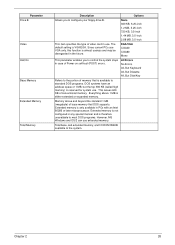
...DOS programs. DOS systems have an address space of 1 MB, but the top 384 KB (called high memory) is either extended or expanded memory. Since current PCs use extended memory. Extended memory is not configured in any special manner and is therefore unavailable to most DOS programs. However, MS Windows... . The default setting is only available in PCs with an Intel 80286 or later microprocessor. Parameter Drive B Video Halt On Base Memory Extended Memory Total Memory Description Options Allows you to control the system stops in case of Power-on self-test (POST) errors. This leaves 640 KB ...
...DOS programs. DOS systems have an address space of 1 MB, but the top 384 KB (called high memory) is either extended or expanded memory. Since current PCs use extended memory. Extended memory is not configured in any special manner and is therefore unavailable to most DOS programs. However, MS Windows... . The default setting is only available in PCs with an Intel 80286 or later microprocessor. Parameter Drive B Video Halt On Base Memory Extended Memory Total Memory Description Options Allows you to control the system stops in case of Power-on self-test (POST) errors. This leaves 640 KB ...
Veriton 5200 Service Guide
Page 39
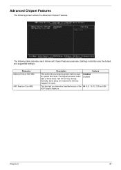
... option lets you determine the effective size of these areas are the default and suggested settings.. Disabled Enabled This item lets you reserve system memory area for memory mapped I/O cards. Chapter 2 30 The chipset accesses code/ data of the 64, 4, 8, 16, 32, 128 and 256 AGP Graphic Aperture. Normally, these areas from...
... option lets you determine the effective size of these areas are the default and suggested settings.. Disabled Enabled This item lets you reserve system memory area for memory mapped I/O cards. Chapter 2 30 The chipset accesses code/ data of the 64, 4, 8, 16, 32, 128 and 256 AGP Graphic Aperture. Normally, these areas from...
Veriton 5200 Service Guide
Page 52
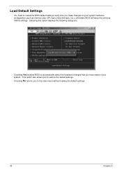
Selecting this option displays the following dialog box: Choosing Yes enables BIOS to automatically detect the hardware changes that you have made in your system hardware configuration (such as memory size, CPU type, hard disk type, etc.); Choosing No returns you to restore the default settings. This option also allows you to the main menu without loading the default settings. 43 Chapter 2 Load Default Settings You need to reload the BIOS default settings every time you make changes to your system. otherwise, BIOS will keep the previous CMOS settings.
Selecting this option displays the following dialog box: Choosing Yes enables BIOS to automatically detect the hardware changes that you have made in your system hardware configuration (such as memory size, CPU type, hard disk type, etc.); Choosing No returns you to restore the default settings. This option also allows you to the main menu without loading the default settings. 43 Chapter 2 Load Default Settings You need to reload the BIOS default settings every time you make changes to your system. otherwise, BIOS will keep the previous CMOS settings.
Veriton 5200 Service Guide
Page 54
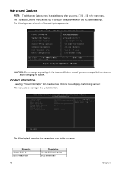
... date 45 Description R01-C0. Advanced Options NOTE: The Advanced Options menu is available only when you are not a qualified technician to configure the system memory and PCI device settings. The following screen shows the Advanced Options parameter: CAUTION: Do not change any settings in the Advanced Options menu if you...
... date 45 Description R01-C0. Advanced Options NOTE: The Advanced Options menu is available only when you are not a qualified technician to configure the system memory and PCI device settings. The following screen shows the Advanced Options parameter: CAUTION: Do not change any settings in the Advanced Options menu if you...
Veriton 5200 Service Guide
Page 62
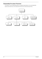
Housing Cover Memory Link Bar CPU PCI and AGP Expansion Cards HDD FDD CD-ROM Power Supply 53 Chapter 3 Disassembly Procedure Flowchart The flowchart on the succeeding page gives you a graphical representation on the entire disassembly sequence and instructs you on the components that need to be removed during servicing.
Housing Cover Memory Link Bar CPU PCI and AGP Expansion Cards HDD FDD CD-ROM Power Supply 53 Chapter 3 Disassembly Procedure Flowchart The flowchart on the succeeding page gives you a graphical representation on the entire disassembly sequence and instructs you on the components that need to be removed during servicing.


