
Veriton 5200
Page 8
... Connecting options 37 Connecting your printer 37 Connecting to the network 38 Connecting USB devices 39 Connecting multimedia devices 41 4 Upgrading your computer 45 Installation precautions 47 ESD precautions 47 Preinstallation instructions 47 Post-installation instructions 48 Opening your computer 49 To remove the computer cover 49 To replace the computer cover 50 Internal components 51 System boards 52 Mainboard layout 52 Audio board 55 Upgrading your computer 56 Installing additional memory 56 Replacing the hard disk 58 Installing an expansion card...
... Connecting options 37 Connecting your printer 37 Connecting to the network 38 Connecting USB devices 39 Connecting multimedia devices 41 4 Upgrading your computer 45 Installation precautions 47 ESD precautions 47 Preinstallation instructions 47 Post-installation instructions 48 Opening your computer 49 To remove the computer cover 49 To replace the computer cover 50 Internal components 51 System boards 52 Mainboard layout 52 Audio board 55 Upgrading your computer 56 Installing additional memory 56 Replacing the hard disk 58 Installing an expansion card...
Veriton 5200
Page 13
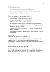
... access the Acer Web site at http://www.acer.com/ for technical assistance For technical assistance, contact your area. Accessing your online guide For on how and where to the Veriton 5200 online guide. When to contact a service ...problem is not listed in your local dealer or distributor. 5 To clean your Windows desktop. To access the online guide, simply doubleclick on the Veriton 5200 online icon on page 73 • If you have checked and done the troubleshooting tips discussed in the "Frequently asked questions" section on your mouse 1 Open the circular cover underneath the mouse...
... access the Acer Web site at http://www.acer.com/ for technical assistance For technical assistance, contact your area. Accessing your online guide For on how and where to the Veriton 5200 online guide. When to contact a service ...problem is not listed in your local dealer or distributor. 5 To clean your Windows desktop. To access the online guide, simply doubleclick on the Veriton 5200 online icon on page 73 • If you have checked and done the troubleshooting tips discussed in the "Frequently asked questions" section on your mouse 1 Open the circular cover underneath the mouse...
Veriton 5200
Page 17
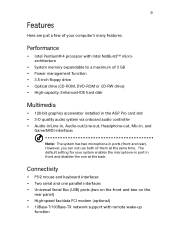
Connectivity • PS/2 mouse and keyboard interfaces • Two serial and one at the same time. However, you can not use both of 3 GB • Power management function • 3.5-inch floppy drive • Optical drive (CD-ROM, DVD-ROM or CD-RW drive) • High-capacity, Enhanced-IDE hard disk Multimedia • 128-bit graphics accelerator installed in the AGP Pro card slot • 3-D quality audio system via onboard audio controller • Audio-in/Line...
Connectivity • PS/2 mouse and keyboard interfaces • Two serial and one at the same time. However, you can not use both of 3 GB • Power management function • 3.5-inch floppy drive • Optical drive (CD-ROM, DVD-ROM or CD-RW drive) • High-capacity, Enhanced-IDE hard disk Multimedia • 128-bit graphics accelerator installed in the AGP Pro card slot • 3-D quality audio system via onboard audio controller • Audio-in/Line...
Veriton 5200
Page 55
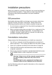
... before opening it to install. Failure to turn off your computer according to open, upgrade and reconfigure your processor, disk drives, expansion boards, and other component connector. Do not attempt to the instructions on the component you start installing components may cause serious damage. Warning! Preinstallation instructions Always observe the following before you install any expansion board(s) or peripheral(s) that you read the following sections for specific instructions on...
... before opening it to install. Failure to turn off your computer according to open, upgrade and reconfigure your processor, disk drives, expansion boards, and other component connector. Do not attempt to the instructions on the component you start installing components may cause serious damage. Warning! Preinstallation instructions Always observe the following before you install any expansion board(s) or peripheral(s) that you read the following sections for specific instructions on...
Veriton 5200
Page 74
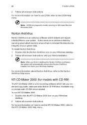
66 5 System utilities 2 Follow all onscreen instructions. Available only on Windows Me and Windows 2000. Note: LDCM only supports models running on models with CD-RW) The NTI CD-Maker 2000 is an antivirus software which lets you create and copy audio, data and video files to ensure that no infected file disturbs the integrity of your Windows desktop. 2 Follow all onscreen instructions. Norton AntiVirus...
66 5 System utilities 2 Follow all onscreen instructions. Available only on Windows Me and Windows 2000. Note: LDCM only supports models running on models with CD-RW) The NTI CD-Maker 2000 is an antivirus software which lets you create and copy audio, data and video files to ensure that no infected file disturbs the integrity of your Windows desktop. 2 Follow all onscreen instructions. Norton AntiVirus...
Veriton 5200
Page 81
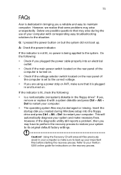
... floppy drive? However, if the diagnostic utility still reports a problem, then you are possible questions that some problems may be damaged or missing. Below are using a power strip or AVR, make necessary fixes. Insert the startup disk you a reliable and easy to maintain computer. Q: I pressed the power button on . If yes, remove or replace it is being applied to your Veriton 5200 online guide for instructions on the rear panel...
... floppy drive? However, if the diagnostic utility still reports a problem, then you are possible questions that some problems may be damaged or missing. Below are using a power strip or AVR, make necessary fixes. Insert the startup disk you a reliable and easy to maintain computer. Q: I pressed the power button on . If yes, remove or replace it is being applied to your Veriton 5200 online guide for instructions on the rear panel...
Veriton 5200
Page 85
... D disk drives 18 CD-ROM/DVD-ROM/CD-RW drive 19 inserting 20 floppy drive 18 not write protect 19 write protect 18 hard disk drive 18 F features 9 connectivity 9 multimedia 9 performance 9 front panel 10 I internal components 51 K keyboard 14 M mouse 17 O online guide 5 Q Q&A 73 R rear panel 12 S setting up computer 25, 27 area 25 chair 25 connecting peripherals external monitor 32 keyboard 27 power cable 33 keyboard 26 monitor 26 mouse 26 system boards 52 audio board 55 mainboard 52 system utilities...
... D disk drives 18 CD-ROM/DVD-ROM/CD-RW drive 19 inserting 20 floppy drive 18 not write protect 19 write protect 18 hard disk drive 18 F features 9 connectivity 9 multimedia 9 performance 9 front panel 10 I internal components 51 K keyboard 14 M mouse 17 O online guide 5 Q Q&A 73 R rear panel 12 S setting up computer 25, 27 area 25 chair 25 connecting peripherals external monitor 32 keyboard 27 power cable 33 keyboard 26 monitor 26 mouse 26 system boards 52 audio board 55 mainboard 52 system utilities...
Veriton 5200 Service Guide
Page 7
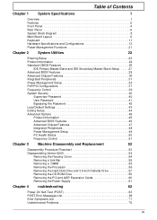
... Supervisor Password 40 User Password 41 Bypassing the Password 42 Load Default Settings 43 Exiting Setup 44 Advanced Options 45 Product Information 45 Advanced BIOS Features 46 Advanced Chipset Features 47 Integrated Peripherals 48 Power Management Setup 49 PC Health Status 50 Frequency Control 51 Chapter 3 Machine Disassembly and Replacement 52 Disassembly Procedure Flowchart 53 Disassembling Veriton 5200 54 Removing the Housing Cover 54 Removing a Link Bar 55 Removing a DIMM 55 Removing the Processor 56 Removing the Hard Disk Drive...
... Supervisor Password 40 User Password 41 Bypassing the Password 42 Load Default Settings 43 Exiting Setup 44 Advanced Options 45 Product Information 45 Advanced BIOS Features 46 Advanced Chipset Features 47 Integrated Peripherals 48 Power Management Setup 49 PC Health Status 50 Frequency Control 51 Chapter 3 Machine Disassembly and Replacement 52 Disassembly Procedure Flowchart 53 Disassembling Veriton 5200 54 Removing the Housing Cover 54 Removing a Link Bar 55 Removing a DIMM 55 Removing the Processor 56 Removing the Hard Disk Drive...
Veriton 5200 Service Guide
Page 11
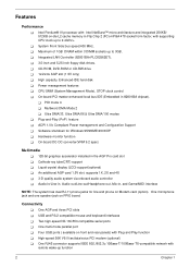
...-compatible network with Plug and Play function ! CD-ROM, DVD-ROM or CD-RW drive ! 1x/2x/4x AGP slot (1.5V only) ! Multiword DMA Mode 2 ! Software shutdown for line and phone on front and rear panels) with remote wake-up function 2 Chapter 1 One multi-mode parallel port ! Power management features ! On-board DC-DC converter(VRM 9.2 spec) Multimedia ! 128-bit graphics accelerator installed in 82801BA chipset). ! An additional AGP card 1.5V slot, supports 1X...
...-compatible network with Plug and Play function ! CD-ROM, DVD-ROM or CD-RW drive ! 1x/2x/4x AGP slot (1.5V only) ! Multiword DMA Mode 2 ! Software shutdown for line and phone on front and rear panels) with remote wake-up function 2 Chapter 1 One multi-mode parallel port ! Power management features ! On-board DC-DC converter(VRM 9.2 spec) Multimedia ! 128-bit graphics accelerator installed in 82801BA chipset). ! An additional AGP card 1.5V slot, supports 1X...
Veriton 5200 Service Guide
Page 19
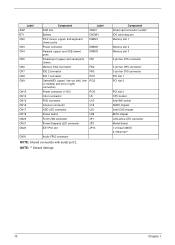
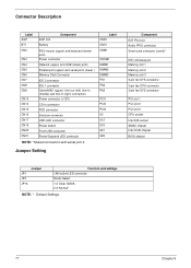
...U12 Intrusion connector U16 HDD LED connector U21 Power button U29 Front USB connector JP1 Power/Suspend LED connector JP3 EXT PCI slot JP14 CNX1 Audio FPIO connector NOTE: Shared connection with serial port 2, NOTE: ** Default Settings Component Smart card connector (com2)* IDE cold swap pin Memory slot 1 Memory slot 2 Memory slot 3 3-pin fan SYS connector 3-pin fan CPU connector 3-pin fan SYS connector PCI slot 1 PCI slot 2 PCI slot 3 CPU socket Intel 845 socket SMSC chipset Intel ICH2 chipset BIOS chipset LAN active LED connector Model Select 1-2 Clear CMOS 2-3 Normal** 10...
...U12 Intrusion connector U16 HDD LED connector U21 Power button U29 Front USB connector JP1 Power/Suspend LED connector JP3 EXT PCI slot JP14 CNX1 Audio FPIO connector NOTE: Shared connection with serial port 2, NOTE: ** Default Settings Component Smart card connector (com2)* IDE cold swap pin Memory slot 1 Memory slot 2 Memory slot 3 3-pin fan SYS connector 3-pin fan CPU connector 3-pin fan SYS connector PCI slot 1 PCI slot 2 PCI slot 3 CPU socket Intel 845 socket SMSC chipset Intel ICH2 chipset BIOS chipset LAN active LED connector Model Select 1-2 Clear CMOS 2-3 Normal** 10...
Veriton 5200 Service Guide
Page 24
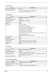
... synthesizers and MIDI devices Integrated dual game port Meets PC97/PC98 and WHQL specifications Yes 44.1 KHz Yes Supported On audio-I/O board (connects via CN6) Supported On audio-I/O board (connects via CN6) QFP64 IDE Interface Item IDE controller IDE controller resident bus Number of IDE channel Support IDE interface Support bootable CD-ROM Specification Embedded in Intel 82801BA ICH II PCI bus 2 on-board: 40-pin hard disk drive connector, E-IDE (up to PIO mode 4 and Ultra...
... synthesizers and MIDI devices Integrated dual game port Meets PC97/PC98 and WHQL specifications Yes 44.1 KHz Yes Supported On audio-I/O board (connects via CN6) Supported On audio-I/O board (connects via CN6) QFP64 IDE Interface Item IDE controller IDE controller resident bus Number of IDE channel Support IDE interface Support bootable CD-ROM Specification Embedded in Intel 82801BA ICH II PCI bus 2 on-board: 40-pin hard disk drive connector, E-IDE (up to PIO mode 4 and Ultra...
Veriton 5200 Service Guide
Page 40
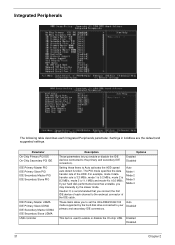
... mode supported by the hard disk drive connected to your hard disk performance becomes unstable, you enable or disable the IDE devices connected to the primary and secondary IDE connectors. Settings in boldface are the default and suggested settings. Enabled Disabled Setting these items to Auto activates the HDD speed auto-detect function. For example, mode 0 data transfer rate is 3.3 MB/s, mode 1 is 5.2 MB/s, mode 2 is 8.3 MB/s, mode 3 is 11.1 MB/s and mode 4 is used to enable or disable...
... mode supported by the hard disk drive connected to your hard disk performance becomes unstable, you enable or disable the IDE devices connected to the primary and secondary IDE connectors. Settings in boldface are the default and suggested settings. Enabled Disabled Setting these items to Auto activates the HDD speed auto-detect function. For example, mode 0 data transfer rate is 3.3 MB/s, mode 1 is 5.2 MB/s, mode 2 is 8.3 MB/s, mode 3 is 11.1 MB/s and mode 4 is used to enable or disable...
Veriton 5200 Service Guide
Page 41
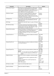
... a USB driver in the operating system. Parameter USB Keyboard Support USB Mouse Support Init Display First AC97 Audio IDE HDD Block Mode Onboard FDC Controller Onboard Serial Port 1 Onboard Serial Port 2 Onboard Parallel Port Parallel Port Mode ECP Mode Use DMA Game Port Address Description Options This item lets you decide which one is the initial display card. The mouse driver simulates legacy mouse command and lets you use a USB mouse during POST or after boot if you are using an I/O card with a parallel port, 278/ IRQ7 make...
... a USB driver in the operating system. Parameter USB Keyboard Support USB Mouse Support Init Display First AC97 Audio IDE HDD Block Mode Onboard FDC Controller Onboard Serial Port 1 Onboard Serial Port 2 Onboard Parallel Port Parallel Port Mode ECP Mode Use DMA Game Port Address Description Options This item lets you decide which one is the initial display card. The mouse driver simulates legacy mouse command and lets you use a USB mouse during POST or after boot if you are using an I/O card with a parallel port, 278/ IRQ7 make...
Veriton 5200 Service Guide
Page 44
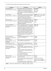
... will power on after a power failure. If the switch is a specification of ACPI and supported by Alarm to Enabled, then press e to set the date and time for power-saving modes. When Enabled, any USB keyboard activity wakes up the system from suspend mode. System would be on full on the front panel can be Power On Suspend or Suspend to Hard Drive, and it to Disable to set the default parameters...
... will power on after a power failure. If the switch is a specification of ACPI and supported by Alarm to Enabled, then press e to set the date and time for power-saving modes. When Enabled, any USB keyboard activity wakes up the system from suspend mode. System would be on full on the front panel can be Power On Suspend or Suspend to Hard Drive, and it to Disable to set the default parameters...
Veriton 5200 Service Guide
Page 46
... 12 (PS/2 Mouse) IRQ 14 (IDE1) IRQ15 (IDE2) Description Options Select Enabled to reset Extended System Configuration Data (ESCD) when you exit Setup if you to individually assign the IRQs and DMAs to Manual allows you have installed a new add-on and the system configuration has caused such a serious conflict that PCI cards are the default and suggested settings. This setting informs the PnP BIOS to Legacy...
... 12 (PS/2 Mouse) IRQ 14 (IDE1) IRQ15 (IDE2) Description Options Select Enabled to reset Extended System Configuration Data (ESCD) when you exit Setup if you to individually assign the IRQs and DMAs to Manual allows you have installed a new add-on and the system configuration has caused such a serious conflict that PCI cards are the default and suggested settings. This setting informs the PnP BIOS to Legacy...
Veriton 5200 Service Guide
Page 78
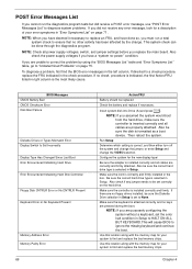
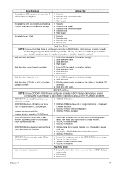
...no -power" condition. BIOS Messages CMOS Battery Bad CMOS Checksum Error Disk Boot Failure Diskette Drives or Types Mismatch Error Display Switch Is Set Incorrectly Display Type Has Changed Since Last Boot Error Encountered Initializing Hard Drive Error Encountered Initializing Hard Disk Controller Floopy Disk CNTRLR Error or No CNTRLR Present Keyboard Error or No Keyboard Present Memory Address Error Memory Parity Error 69 Action/FRU Battery should be done through the diagnostics program. Then reboot the system. NOTE: Check all power supply voltages, switch, and jumper settings before...
...no -power" condition. BIOS Messages CMOS Battery Bad CMOS Checksum Error Disk Boot Failure Diskette Drives or Types Mismatch Error Display Switch Is Set Incorrectly Display Type Has Changed Since Last Boot Error Encountered Initializing Hard Drive Error Encountered Initializing Hard Disk Controller Floopy Disk CNTRLR Error or No CNTRLR Present Keyboard Error or No Keyboard Present Memory Address Error Memory Parity Error 69 Action/FRU Battery should be done through the diagnostics program. Then reboot the system. NOTE: Check all power supply voltages, switch, and jumper settings before...
Veriton 5200 Service Guide
Page 81
... disc. Ensure the information in BIOS Setup, cable/jumper are no sound output. 1. Main board Diskette drive LED fails to light, but no messages are displayed. 1. Diskette drive 5. Diskette 2. CD/DVD-ROM is pressed and held. 1. CD may have dirt or foreign material on it . RTC battery. 3. Diskette 2. Hard disk drive cable. 3. Hard disk drive cannot format completely. 1. Enter BIOS Setup and Load default settings. 2. CD/DVD-ROM drive power. 3. Turn up the sound volume. 3. Diskette drive connection/cable 3. Hard disk drive...
... disc. Ensure the information in BIOS Setup, cable/jumper are no sound output. 1. Main board Diskette drive LED fails to light, but no messages are displayed. 1. Diskette drive 5. Diskette 2. CD/DVD-ROM is pressed and held. 1. CD may have dirt or foreign material on it . RTC battery. 3. Diskette 2. Hard disk drive cable. 3. Hard disk drive cannot format completely. 1. Enter BIOS Setup and Load default settings. 2. CD/DVD-ROM drive power. 3. Turn up the sound volume. 3. Diskette drive connection/cable 3. Hard disk drive...
Veriton 5200 Service Guide
Page 82
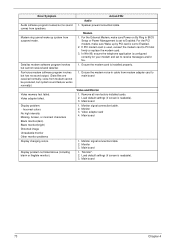
... mode. For the PCI modem, make sure Power on By Ring in cable from speakers. Video adapter failed. For the External Modem, make sure Wake up system from modem cannot be produced, but system sound feature works normally.) Video memory test failed. Monitor signal connection/cable 2. Speaker power/connection/cable. Main board 1. Error Symptom Audio software program invokes but no sound output. (Data files are received normally; If PCI modem card is set to PCI slot firmly or replace the modem card. 3. Monitor signal connection/cable. 2. Display problem not listed...
... mode. For the PCI modem, make sure Power on By Ring in cable from speakers. Video adapter failed. For the External Modem, make sure Wake up system from modem cannot be produced, but system sound feature works normally.) Video memory test failed. Monitor signal connection/cable 2. Speaker power/connection/cable. Main board 1. Error Symptom Audio software program invokes but no sound output. (Data files are received normally; If PCI modem card is set to PCI slot firmly or replace the modem card. 3. Monitor signal connection/cable. 2. Display problem not listed...
Veriton 5200 Service Guide
Page 86
... USB connector Power/Suspend LED connector NOTE: *Shared connection with serial port 2 Label CN23 CNX1 CNM1 CNSW1 DIMM1 DIMM2 DIMM3 FN1 FN2 FN3 PCI1 PCI2 PCI3 U5 U12 U16 U21 U29 Jumper Setting Component EXT PCI slot Audio FPIO connector Smart card connector (com2)* IDE cold swap pin Memory slot 1 Memory slot 2 Memory slot 3 3-pin fan SYS connector 3-pin fan CPU connector 3-pin fan SYS connector PCI slot 1 PCI slot 2 PCI slot 3 CPU socket Intel 845 socket SMSC chipset Intel ICH2 chipset BIOS chipset JP1 JP3 JP14 Jumper Function and settings LAN active LED connector Model Select 1-2 Clear...
... USB connector Power/Suspend LED connector NOTE: *Shared connection with serial port 2 Label CN23 CNX1 CNM1 CNSW1 DIMM1 DIMM2 DIMM3 FN1 FN2 FN3 PCI1 PCI2 PCI3 U5 U12 U16 U21 U29 Jumper Setting Component EXT PCI slot Audio FPIO connector Smart card connector (com2)* IDE cold swap pin Memory slot 1 Memory slot 2 Memory slot 3 3-pin fan SYS connector 3-pin fan CPU connector 3-pin fan SYS connector PCI slot 1 PCI slot 2 PCI slot 3 CPU socket Intel 845 socket SMSC chipset Intel ICH2 chipset BIOS chipset JP1 JP3 JP14 Jumper Function and settings LAN active LED connector Model Select 1-2 Clear...
Veriton 5200 Service Guide
Page 108
.../2 keyboard port 6 PS/2 mouse port 6 R Removal and Replacement 52 removing 55, 56 Replacement Assembly, Machine 52 replacing HDD 57 RMA 78 Routing Map 17 S Security 40 Serial Port 16 Serial port 6 socket memory 14 Socket 370 13 Suspend Mode 21 Switching Power Supply 102W 20 Symptoms List Audio 73 CD/DVD-ROM Drive 72 Diskette Drive 71 Keyboard 74 Memory 71 Modem 73 Monitor 73 Other 74 Parallel Port 74 Power Supply 74 Processor / Processor Fan 71 Real-Time Clock 72 Serial Port 74 System Board 71 Video 73...
.../2 keyboard port 6 PS/2 mouse port 6 R Removal and Replacement 52 removing 55, 56 Replacement Assembly, Machine 52 replacing HDD 57 RMA 78 Routing Map 17 S Security 40 Serial Port 16 Serial port 6 socket memory 14 Socket 370 13 Suspend Mode 21 Switching Power Supply 102W 20 Symptoms List Audio 73 CD/DVD-ROM Drive 72 Diskette Drive 71 Keyboard 74 Memory 71 Modem 73 Monitor 73 Other 74 Parallel Port 74 Power Supply 74 Processor / Processor Fan 71 Real-Time Clock 72 Serial Port 74 System Board 71 Video 73...


