
Veriton 5200
Page 8
... options 37 Connecting your printer 37 Connecting to the network 38 Connecting USB devices 39 Connecting multimedia devices 41 4 Upgrading your computer 45 Installation precautions 47 ESD precautions 47 Preinstallation instructions 47 Post-installation instructions 48 Opening your computer 49 ... cover 49 To replace the computer cover 50 Internal components 51 System boards 52 Mainboard layout 52 Audio board 55 Upgrading your computer 56 Installing additional memory 56 Replacing the hard disk 58 Installing an expansion card 60 5 System utilities ...
... options 37 Connecting your printer 37 Connecting to the network 38 Connecting USB devices 39 Connecting multimedia devices 41 4 Upgrading your computer 45 Installation precautions 47 ESD precautions 47 Preinstallation instructions 47 Post-installation instructions 48 Opening your computer 49 ... cover 49 To replace the computer cover 50 Internal components 51 System boards 52 Mainboard layout 52 Audio board 55 Upgrading your computer 56 Installing additional memory 56 Replacing the hard disk 58 Installing an expansion card 60 5 System utilities ...
Veriton 5200
Page 13
You may also access the Acer Web site at http://www.acer.com/ for technical assistance For technical assistance, contact your local dealer or distributor. To access the online guide, simply doubleclick on the Veriton 5200 online icon on page 73 • If your problem is not listed in your ... the Veriton 5200 online guide. 5 To clean your Windows desktop. Accessing your online guide For on-the-go help information about your computer, refer to contact the service centers available in the "Frequently asked questions" section on page 73 • If you want to replace or upgrade any ...
You may also access the Acer Web site at http://www.acer.com/ for technical assistance For technical assistance, contact your local dealer or distributor. To access the online guide, simply doubleclick on the Veriton 5200 online icon on page 73 • If your problem is not listed in your ... the Veriton 5200 online guide. 5 To clean your Windows desktop. Accessing your online guide For on-the-go help information about your computer, refer to contact the service centers available in the "Frequently asked questions" section on page 73 • If you want to replace or upgrade any ...
Veriton 5200
Page 26
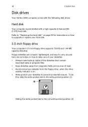
... drives: Hard disk Your computer is on how to carry around. 18 2 System tour Disk drives Your Veriton 5200 computer comes with a high-capacity Enhanced-IDE (E-IDE) hard disk. Here are compact, lightweight, and easy to upgrade or replace your hard disk. 3.5-inch floppy drive Your computer's 3.5-inch floppy drive supports 720-KB...
... drives: Hard disk Your computer is on how to carry around. 18 2 System tour Disk drives Your Veriton 5200 computer comes with a high-capacity Enhanced-IDE (E-IDE) hard disk. Here are compact, lightweight, and easy to upgrade or replace your hard disk. 3.5-inch floppy drive Your computer's 3.5-inch floppy drive supports 720-KB...
Veriton 5200
Page 53
4 Upgrading your computer
4 Upgrading your computer
Veriton 5200
Page 54
This chapter contains instructions on how to upgrade your computer and basic information about your system boards that you will find helpful when performing the upgrade process.
This chapter contains instructions on how to upgrade your computer and basic information about your system boards that you will find helpful when performing the upgrade process.
Veriton 5200
Page 55
... a wrist strap is not available, maintain contact with preinstallation and post-installation instructions. Preinstallation instructions Always observe the following sections. Do not attempt to open, upgrade and reconfigure your processor, disk drives, expansion boards, and other component connector. Failure to turn off your computer according to the instructions on the component...
... a wrist strap is not available, maintain contact with preinstallation and post-installation instructions. Preinstallation instructions Always observe the following sections. Do not attempt to open, upgrade and reconfigure your processor, disk drives, expansion boards, and other component connector. Failure to turn off your computer according to the instructions on the component...
Veriton 5200
Page 56
by-step instructions in their respective sections. 2 Replace any expansion board(s) or peripheral(s) that all components are installed according to it that you removed earlier. 3 Connect the necessary cables. 4 Replace the computer cover. 5 Turn on the computer. 48 4 Upgrading your computer Post-installation instructions Observe the following after installing a computer component: 1 See to the step-
by-step instructions in their respective sections. 2 Replace any expansion board(s) or peripheral(s) that all components are installed according to it that you removed earlier. 3 Connect the necessary cables. 4 Replace the computer cover. 5 Turn on the computer. 48 4 Upgrading your computer Post-installation instructions Observe the following after installing a computer component: 1 See to the step-
Veriton 5200
Page 58
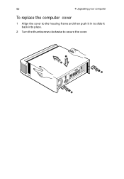
50 4 Upgrading your computer To replace the computer cover 1 Align the cover to the housing frame and then push it in to slide it back into place. 2 Turn the thumbscrews clockwise to secure the cover.
50 4 Upgrading your computer To replace the computer cover 1 Align the cover to the housing frame and then push it in to slide it back into place. 2 Turn the thumbscrews clockwise to secure the cover.
Veriton 5200
Page 60
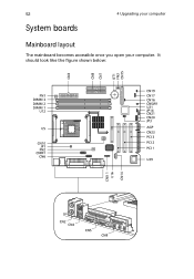
It should look like the figure shown below: 52 System boards 4 Upgrading your computer Mainboard layout The mainboard becomes accessible once you open your computer.
It should look like the figure shown below: 52 System boards 4 Upgrading your computer Mainboard layout The mainboard becomes accessible once you open your computer.
Veriton 5200
Page 62
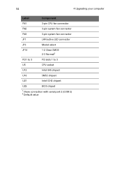
54 4 Upgrading your computer Label Component FN1 3-pin CPU fan connector FN2 3-pin system fan connector FN3 3-pin system fan connector JP1 LAN active LED connector JP3 Model select JP14 1-2 Clear CMOS 2-3 Normal2 PCI1 to 3 PCI slots 1 to 3 U5 CPU socket U12 Intel 845 chipset U16 SMSC chipset U21 Intel ICH2 chipset U29 BIOS chipset 1 Share connection with serial port 2 (COM 2) 2 Default value
54 4 Upgrading your computer Label Component FN1 3-pin CPU fan connector FN2 3-pin system fan connector FN3 3-pin system fan connector JP1 LAN active LED connector JP3 Model select JP14 1-2 Clear CMOS 2-3 Normal2 PCI1 to 3 PCI slots 1 to 3 U5 CPU socket U12 Intel 845 chipset U16 SMSC chipset U21 Intel ICH2 chipset U29 BIOS chipset 1 Share connection with serial port 2 (COM 2) 2 Default value
Veriton 5200
Page 64
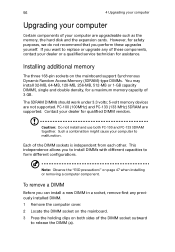
...) and PC-133 (133 MHz) SDRAM are not supported. To remove a DIMM Before you perform these components, contact your computer are upgradeable such as the memory, the hard disk and the expansion cards. Such a combination might cause your dealer for qualified DIMM vendors. The SDRAM... safety purposes, we do not recommend that you can install a new DIMM in a socket, remove first any of these upgrades yourself. 56 4 Upgrading your computer Upgrading your computer Certain components of your dealer or a qualified service technician for assistance. Caution: Do not install and use both ...
...) and PC-133 (133 MHz) SDRAM are not supported. To remove a DIMM Before you perform these components, contact your computer are upgradeable such as the memory, the hard disk and the expansion cards. Such a combination might cause your dealer for qualified DIMM vendors. The SDRAM... safety purposes, we do not recommend that you can install a new DIMM in a socket, remove first any of these upgrades yourself. 56 4 Upgrading your computer Upgrading your computer Certain components of your dealer or a qualified service technician for assistance. Caution: Do not install and use both ...
Veriton 5200
Page 66
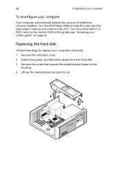
For more information on page 5). 58 4 Upgrading your computer To reconfigure your online guide" on BIOS, refer to the housing. 4 Lift up the metal bracket and pull it . Replacing the hard disk ... the computer cover. 2 Detach the power and disk drive cables from the hard disk. 3 Remove the screw that secures the metal bracket frame to the Veriton 5200 online guide (see "Accessing your computer Your computer automatically detects the amount of it out. Run the BIOS Setup utility to view the new value...
For more information on page 5). 58 4 Upgrading your computer To reconfigure your online guide" on BIOS, refer to the housing. 4 Lift up the metal bracket and pull it . Replacing the hard disk ... the computer cover. 2 Detach the power and disk drive cables from the hard disk. 3 Remove the screw that secures the metal bracket frame to the Veriton 5200 online guide (see "Accessing your computer Your computer automatically detects the amount of it out. Run the BIOS Setup utility to view the new value...
Veriton 5200
Page 68
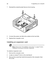
60 4 Upgrading your computer 7 Reinstall the metal bracket frame to the housing. 8 Connect the power and disk drive cables to the computer. Save the screw. Installing an expansion card Note: Observe the "Preinstallation instructions" on the mainboard. 3 Remove the screw that holds the bracket to the hard disk. 9 Replace the computer cover. To install an expansion card: 1 Remove the computer cover. 2 Locate an empty PCI slot on page 47 when installing or removing a computer component.
60 4 Upgrading your computer 7 Reinstall the metal bracket frame to the housing. 8 Connect the power and disk drive cables to the computer. Save the screw. Installing an expansion card Note: Observe the "Preinstallation instructions" on the mainboard. 3 Remove the screw that holds the bracket to the hard disk. 9 Replace the computer cover. To install an expansion card: 1 Remove the computer cover. 2 Locate an empty PCI slot on page 47 when installing or removing a computer component.
Veriton 5200
Page 70
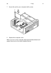
62 4 Upgrading your computer 7 Secure the card to the newly-installed devices. When you turn on the computer, BIOS automatically detects and assigns resources to your computer with a screw. 8 Replace the computer cover.
62 4 Upgrading your computer 7 Secure the card to the newly-installed devices. When you turn on the computer, BIOS automatically detects and assigns resources to your computer with a screw. 8 Replace the computer cover.
Veriton 5200
Page 85
... 67 reinstalling programs 69 VariSpeed 67 T technical assistance 5 troubleshooting 73 turning off computer 36 software shutdown 36 suspend mode 36 turning on computer 34 34 U upgrade add memory 56 install DIMM 57 reconfigure computer 58
... 67 reinstalling programs 69 VariSpeed 67 T technical assistance 5 troubleshooting 73 turning off computer 36 software shutdown 36 suspend mode 36 turning on computer 34 34 U upgrade add memory 56 install DIMM 57 reconfigure computer 58
Veriton 5200 Service Guide
Page 12
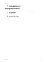
Accessible I/O ports ! Expansion ! 3 PCI slots + 3 DIMM slots + 1 AGP slot ! Separate computer stand and rubber stands for quick and easy positioning ! Low emission and low radiation Chapter 1 3 Smooth and stylish design ! Mini-tower form factor ! Upgradeable memory and hard disk Human-centric design and ergonomics ! Space-saver solution !
Accessible I/O ports ! Expansion ! 3 PCI slots + 3 DIMM slots + 1 AGP slot ! Separate computer stand and rubber stands for quick and easy positioning ! Low emission and low radiation Chapter 1 3 Smooth and stylish design ! Mini-tower form factor ! Upgradeable memory and hard disk Human-centric design and ergonomics ! Space-saver solution !
Veriton 5200 Service Guide
Page 22
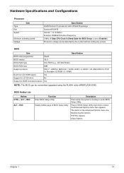
... Boot from CD-ROM feature Yes Support to LS-120 drive No Support to BIOS boot block feature Yes NOTE: The BIOS can be overwritten/upgraded using the FLASH utility (AWDFLASH.EXE). Press in Sleep State the BIOS Setup is booting to Enabled.) Processor voltage can be detected by the system...
... Boot from CD-ROM feature Yes Support to LS-120 drive No Support to BIOS boot block feature Yes NOTE: The BIOS can be overwritten/upgraded using the FLASH utility (AWDFLASH.EXE). Press in Sleep State the BIOS Setup is booting to Enabled.) Processor voltage can be detected by the system...
Veriton 5200 Service Guide
Page 107
... 19 CMOS Setup 22 Compatibility Test 88 Connectors 76 Description 77 description 77 controllers 19 audio 15 serial port 16 CPU removing 55, 56 CPU upgrade removing 55, 56 CRT Monitor port 7 Current 20 Index Index D Device Standby Mode 21 disassembly CD-ROM Drive 59 Power Supply 61 Disk Drives 25...
... 19 CMOS Setup 22 Compatibility Test 88 Connectors 76 Description 77 description 77 controllers 19 audio 15 serial port 16 CPU removing 55, 56 CPU upgrade removing 55, 56 CRT Monitor port 7 Current 20 Index Index D Device Standby Mode 21 disassembly CD-ROM Drive 59 Power Supply 61 Disk Drives 25...


