
Veriton 3500G
Page 5
...you to qualified service personnel. 11 Unplug this product from children and dispose of used batteries promptly. 14 Use only the proper type of power supply cord set (provided in your accessories box) for service. 12 Replace the battery with the same type as the product's battery we recommend.... properly. Keep them in damage and will often require extensive work by the operating instructions since improper adjustment of fire or explosion. When the power cord or plug is 15 feet (4.6 meters). Batteries may present a risk of other risks. AVOID EXPOSURE TO BEAM. If the product has...
...you to qualified service personnel. 11 Unplug this product from children and dispose of used batteries promptly. 14 Use only the proper type of power supply cord set (provided in your accessories box) for service. 12 Replace the battery with the same type as the product's battery we recommend.... properly. Keep them in damage and will often require extensive work by the operating instructions since improper adjustment of fire or explosion. When the power cord or plug is 15 feet (4.6 meters). Batteries may present a risk of other risks. AVOID EXPOSURE TO BEAM. If the product has...

Veriton 3500G
Page 23
13 Rear panel Your computer's rear panel consists of the following: Label 1 2 3 4 Icon 5 6 7 8 9 Color Green Component Power supply Voltage selector switch Keyhole PS/2 mouse port Teal or Turquoise Burgundy Power jack (for external speakers) Serial port Parallel/Printer port Blue Monitor port White Network port
13 Rear panel Your computer's rear panel consists of the following: Label 1 2 3 4 Icon 5 6 7 8 9 Color Green Component Power supply Voltage selector switch Keyhole PS/2 mouse port Teal or Turquoise Burgundy Power jack (for external speakers) Serial port Parallel/Printer port Blue Monitor port White Network port

Veriton 3500G
Page 65
55 Internal components The figure below shows what your computer looks like once you remove the cover: Number 1 2 3 4 5 6 7 8 Component 3.5-inch floppy drive CD-ROM/DVD-ROM/CD-RW drive Drive frame Power supply Mainboard see note VGA card Modem card Expansion slot Note: The mainboard model shown in the figure above may not be exactly the same with the one found in your computer.
55 Internal components The figure below shows what your computer looks like once you remove the cover: Number 1 2 3 4 5 6 7 8 Component 3.5-inch floppy drive CD-ROM/DVD-ROM/CD-RW drive Drive frame Power supply Mainboard see note VGA card Modem card Expansion slot Note: The mainboard model shown in the figure above may not be exactly the same with the one found in your computer.
Veriton 3500G/5500G/7500G Service Guide
Page 8
... 79 Removing the LED Activity Indicators 80 Removing the Power Supply 81 Removing the CPU Fan Sink 81 Removing and Installing the Processor 82 Removing the System Main board 83 Removing the I/O Port Bracket 83 Veriton 5500/ 5500G Disassembly Procedure Flowchart 84 Disassembling the Veriton 5500/ 5500G 85 Open the Housing Cover 85 Removing...
... 79 Removing the LED Activity Indicators 80 Removing the Power Supply 81 Removing the CPU Fan Sink 81 Removing and Installing the Processor 82 Removing the System Main board 83 Removing the I/O Port Bracket 83 Veriton 5500/ 5500G Disassembly Procedure Flowchart 84 Disassembling the Veriton 5500/ 5500G 85 Open the Housing Cover 85 Removing...

Veriton 3500G/5500G/7500G Service Guide
Page 16
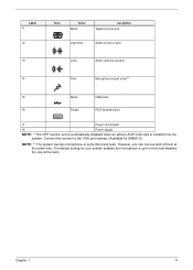
Rear Panel-Veriton 3500/3500G Label 1 2 3 4 Icon Color Green Description Power supply Voltage selector switch Keyhole PS/2 mouse port 5 Power Jack (for external speakers) 6 Teal or Turquoise Serial port 7 Burgundy Parallel/Printer port 8 Blue CRT/LCD monitor port* 9 White Network port 10 Black Modem line and Telephone port 11 6 Power cord socket Veriton 3500/5500/7500
Rear Panel-Veriton 3500/3500G Label 1 2 3 4 Icon Color Green Description Power supply Voltage selector switch Keyhole PS/2 mouse port 5 Power Jack (for external speakers) 6 Teal or Turquoise Serial port 7 Burgundy Parallel/Printer port 8 Blue CRT/LCD monitor port* 9 White Network port 10 Black Modem line and Telephone port 11 6 Power cord socket Veriton 3500/5500/7500
Veriton 3500G/5500G/7500G Service Guide
Page 21
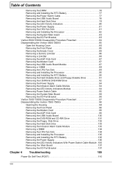
The default setting for S88M/ G) NOTE: ** The system has two microphone-in port (rear)** 15 Black USB ports 16 Purple PS/2 keyboard port 17 Power cord socket 18 Power supply NOTE: * The CRT monitor port is automatically disabled when an add-on AGP VGA card is installed into the system. Connect the monitor to...
The default setting for S88M/ G) NOTE: ** The system has two microphone-in port (rear)** 15 Black USB ports 16 Purple PS/2 keyboard port 17 Power cord socket 18 Power supply NOTE: * The CRT monitor port is automatically disabled when an add-on AGP VGA card is installed into the system. Connect the monitor to...
Veriton 3500G/5500G/7500G Service Guide
Page 24
Rear Panel-Veriton 7500/7500G Label 1 2 3 4 5 6 7 Icon Color Burgundy Description Voltage Selector Switch Power cord socket Parallel/printer port White Network port Green Power jack (for external speakers) Power supply PS/2 mouse port 8 Purple PS/2 keyboard port 14 Veriton 3500/5500/7500
Rear Panel-Veriton 7500/7500G Label 1 2 3 4 5 6 7 Icon Color Burgundy Description Voltage Selector Switch Power cord socket Parallel/printer port White Network port Green Power jack (for external speakers) Power supply PS/2 mouse port 8 Purple PS/2 keyboard port 14 Veriton 3500/5500/7500

Veriton 3500G/5500G/7500G Service Guide
Page 42
... (peak to peak) 2.0G Mechanical Specifications Item Dimensions Weight One 3.5 FDD and one 3.5 HDD (without packing) Specification 244(L)X 244(W)x18mm(H) Depends on local configuration Switching Power Supply A-1 Input frequency 50Hz 60Hz Normal Frequency 47Hz to 53Hz 57Hz to 63Hz Frequency Variation Range A-2 Input voltage Nominal Voltage 100 - 120 VRMS 200 - 240 VRMS...
... (peak to peak) 2.0G Mechanical Specifications Item Dimensions Weight One 3.5 FDD and one 3.5 HDD (without packing) Specification 244(L)X 244(W)x18mm(H) Depends on local configuration Switching Power Supply A-1 Input frequency 50Hz 60Hz Normal Frequency 47Hz to 53Hz 57Hz to 63Hz Frequency Variation Range A-2 Input voltage Nominal Voltage 100 - 120 VRMS 200 - 240 VRMS...

Veriton 3500G/5500G/7500G Service Guide
Page 43
Output Requirements +5V +12V -12V +3.3V +5Vaux +5% +5% +10% +5% +5% Regulation NOTE: 1. +5V & +3.3V total power is 145W power supply) ! Measure at line input 90 VRMS and maximum load condition. This "4A" includes the outlet supply current: 2A ! A-3 Input current Input Current 4A 3A 90 -132 VRMS 180 - 264 VRMS Measuring Range (This is 80W max . 8A 10A 0.3A 10A 3A Current Rating (Max) Chapter 1 33
Output Requirements +5V +12V -12V +3.3V +5Vaux +5% +5% +10% +5% +5% Regulation NOTE: 1. +5V & +3.3V total power is 145W power supply) ! Measure at line input 90 VRMS and maximum load condition. This "4A" includes the outlet supply current: 2A ! A-3 Input current Input Current 4A 3A 90 -132 VRMS 180 - 264 VRMS Measuring Range (This is 80W max . 8A 10A 0.3A 10A 3A Current Rating (Max) Chapter 1 33
Veriton 3500G/5500G/7500G Service Guide
Page 81
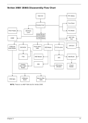
Veriton 3500/ 3500G Disassembly Flow Chart Main Unit RTC Battery Power Supply DIMM EMI Audio Cover Housing Cover Rotate Bracket W/ DVD-ROM & FDD Module Front Panel Front Bezel AGP VGA Card USB/Audio Board Module DVD-ROM Power switch cable HDD Module CPU Fan Sink LAN Card FDD Intrusion Alarm Cable Module HDD Bracket HDD CPU Main Board LED Activity Indicators I/O port Bracket USB Cable USB/Audio Board Memory Stick Cable NOTE: There is no AGP VGA slot for Veriton 3500. Chapter 3 71
Veriton 3500/ 3500G Disassembly Flow Chart Main Unit RTC Battery Power Supply DIMM EMI Audio Cover Housing Cover Rotate Bracket W/ DVD-ROM & FDD Module Front Panel Front Bezel AGP VGA Card USB/Audio Board Module DVD-ROM Power switch cable HDD Module CPU Fan Sink LAN Card FDD Intrusion Alarm Cable Module HDD Bracket HDD CPU Main Board LED Activity Indicators I/O port Bracket USB Cable USB/Audio Board Memory Stick Cable NOTE: There is no AGP VGA slot for Veriton 3500. Chapter 3 71

Veriton 3500G/5500G/7500G Service Guide
Page 91
... from the FDD drive and the DVD-ROM power connector from the hard disk drive. 4. Disconnect the main power connector and 12 Volt. See "Removing the FDD and DVD Frame" on both sides of the fan sink. . Disconnect the fan sink cable from the ...-ROM drive. 3. See "Removing the Housing Cover" on page 72. 2. See "Removing the Housing Cover" on page 72 2. Remove the three screws that hold the power supply to the housing and detach the power supply from the main board. Chapter 3 81 power connector from the housing Removing the CPU Fan Sink 1. Removing the...
... from the FDD drive and the DVD-ROM power connector from the hard disk drive. 4. Disconnect the main power connector and 12 Volt. See "Removing the FDD and DVD Frame" on both sides of the fan sink. . Disconnect the fan sink cable from the ...-ROM drive. 3. See "Removing the Housing Cover" on page 72. 2. See "Removing the Housing Cover" on page 72 2. Remove the three screws that hold the power supply to the housing and detach the power supply from the main board. Chapter 3 81 power connector from the housing Removing the CPU Fan Sink 1. Removing the...
Veriton 3500G/5500G/7500G Service Guide
Page 94
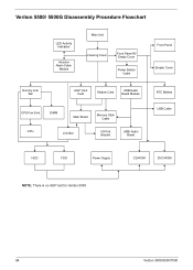
Veriton 5500/ 5500G Disassembly Procedure Flowchart LED Activity Indicators Intrusion Alarm Cable Module Main Unit Housing Cover Front Panel W/ Empty Cover Power Switch Cable Front Panel Empter Cover Dummy Link Bar AGP VGA Card Modem Card USB/Audio Board Module CPU Fan Sink DIMM Main Board Memory Stick Cable CPU Link Bar I/O Port Bracket USB/ Audio Board RTC Battery USB Cable HDD FDD Power Supply CD-ROM DVD-ROM NOTE: There is no AGP slot for Veriton 5500. 84 Veriton 3500/5500/7500
Veriton 5500/ 5500G Disassembly Procedure Flowchart LED Activity Indicators Intrusion Alarm Cable Module Main Unit Housing Cover Front Panel W/ Empty Cover Power Switch Cable Front Panel Empter Cover Dummy Link Bar AGP VGA Card Modem Card USB/Audio Board Module CPU Fan Sink DIMM Main Board Memory Stick Cable CPU Link Bar I/O Port Bracket USB/ Audio Board RTC Battery USB Cable HDD FDD Power Supply CD-ROM DVD-ROM NOTE: There is no AGP slot for Veriton 5500. 84 Veriton 3500/5500/7500

Veriton 3500G/5500G/7500G Service Guide
Page 104
... Disconnect the FDD power connector from the FDD drive and the HDD power connector from DVD- Disconnect the CD-RW power connector from CD-RW drive and DVD-ROM power connector from the HDD.. 5. ROM drive. 6. Remove the four screws that hold the power supply to release the ...the module from the main board. Disconnect the main power connector and 12 Volt. power connector from the housing. 94 Veriton 3500/5500/7500 Removing the Power Supply 1. Press the LED activity indicators module to the housing and detach the power supply from the housing. Removing the LED Activity Indicators Module...
... Disconnect the FDD power connector from the FDD drive and the HDD power connector from DVD- Disconnect the CD-RW power connector from CD-RW drive and DVD-ROM power connector from the HDD.. 5. ROM drive. 6. Remove the four screws that hold the power supply to release the ...the module from the main board. Disconnect the main power connector and 12 Volt. power connector from the housing. 94 Veriton 3500/5500/7500 Removing the Power Supply 1. Press the LED activity indicators module to the housing and detach the power supply from the housing. Removing the LED Activity Indicators Module...
Veriton 3500G/5500G/7500G Service Guide
Page 107
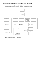
Veriton 7500/ 7500G Disassembly Procedure Flowchart The flowchart on the succeeding page gives you a graphical representation on the entire disassembly sequence and instructs you on the components that need to be removed during servicing. CD-RW/ DVD-ROM CPU Fan Sink CPU Chapter 3 97 Main Unit Left Panel FDD Module RTC Battery Right Panel AGP VGA Card Modem Card HDD Module DIMM Front Panel Main Board Power Supply USB/Audio Board Intrusion Alarm Cable LED Activity Indicators W/ Power Swtich Cable Module NOTE: There is no AGP VGA Slot for Veriton 7500.
Veriton 7500/ 7500G Disassembly Procedure Flowchart The flowchart on the succeeding page gives you a graphical representation on the entire disassembly sequence and instructs you on the components that need to be removed during servicing. CD-RW/ DVD-ROM CPU Fan Sink CPU Chapter 3 97 Main Unit Left Panel FDD Module RTC Battery Right Panel AGP VGA Card Modem Card HDD Module DIMM Front Panel Main Board Power Supply USB/Audio Board Intrusion Alarm Cable LED Activity Indicators W/ Power Swtich Cable Module NOTE: There is no AGP VGA Slot for Veriton 7500.

Veriton 3500G/5500G/7500G Service Guide
Page 116
... drive and the HDD power connector from the main board. 106 Veriton 3500/5500/7500 Disconnect the CD-RW power connector from the CD-RW drive and DVD-ROM power connector from the housing . 4. See "Removing the Front Panel" on page 98 2. Removing the Power Supply 1. Removing the LED Activity Indicators With Power Switch Cable Module 1. See...
... drive and the HDD power connector from the main board. 106 Veriton 3500/5500/7500 Disconnect the CD-RW power connector from the CD-RW drive and DVD-ROM power connector from the housing . 4. See "Removing the Front Panel" on page 98 2. Removing the Power Supply 1. Removing the LED Activity Indicators With Power Switch Cable Module 1. See...
Veriton 3500G/5500G/7500G Service Guide
Page 126
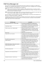
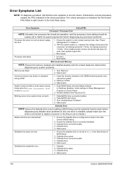
...FRU, and have done so, you must run a total system check to ensure that CMOS has become corrupt. NOTE: Check all power supply voltages, switch, and jumper settings before you are unable to correct the problem by the change the Video selection. If you replace the...Keyboard Present Keyboard is installed correctly. Checksum of CPU. Determine which setting is attached correctly and no -power" condition. The system may run . Veriton 3500/5500/7500 Also check the power supply voltages if you have caused this error. Contact your system dealer for a description of your error ...
...FRU, and have done so, you must run a total system check to ensure that CMOS has become corrupt. NOTE: Check all power supply voltages, switch, and jumper settings before you are unable to correct the problem by the change the Video selection. If you replace the...Keyboard Present Keyboard is installed correctly. Checksum of CPU. Determine which setting is attached correctly and no -power" condition. The system may run . Veriton 3500/5500/7500 Also check the power supply voltages if you have caused this error. Contact your system dealer for a description of your error ...
Veriton 3500G/5500G/7500G Service Guide
Page 128
... set to master.) Media and drive are clean before diagnosing any system problems. Memory test failed. 1. Main board. 118 Veriton 3500/5500/7500 See "Power Management" in the DIMM sockets properly, then reboot the system. 2. If the reading shows normal, but fails to match ... and its speed requirement before diagnosing any processor problems. Processor fan does not run but power supply fan runs. 1. system does not work . 1. Diskette/IDE disk drives 3. With the system power on, measure the voltage of processor fan connector. Enter BIOS Setup and load default settings...
... set to master.) Media and drive are clean before diagnosing any system problems. Memory test failed. 1. Main board. 118 Veriton 3500/5500/7500 See "Power Management" in the DIMM sockets properly, then reboot the system. 2. If the reading shows normal, but fails to match ... and its speed requirement before diagnosing any processor problems. Processor fan does not run but power supply fan runs. 1. system does not work . 1. Diskette/IDE disk drives 3. With the system power on, measure the voltage of processor fan connector. Enter BIOS Setup and load default settings...
Veriton 3500G/5500G/7500G Service Guide
Page 131
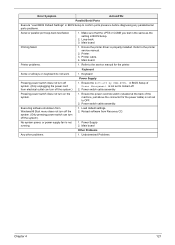
... problems. 1. Undetermined Problems Chapter 4 121 Loop-back. 3. Reload software from Windows98 Start menu does not turn off the system. (Only pressing power switch can turn on keyboard do not work. 1. Power Supply 2. Printing failed. 1. Printer cable. 4. Keyboard Some or all keys on the system. 1. Printer. 3. Refer to confirm ports presence before diagnosing any...
... problems. 1. Undetermined Problems Chapter 4 121 Loop-back. 3. Reload software from Windows98 Start menu does not turn off the system. (Only pressing power switch can turn on keyboard do not work. 1. Power Supply 2. Printing failed. 1. Printer cable. 4. Keyboard Some or all keys on the system. 1. Printer. 3. Refer to confirm ports presence before diagnosing any...
Veriton 3500G/5500G/7500G Service Guide
Page 132
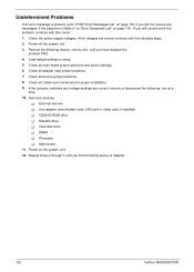
...Hard disk drive ! Processor ! Main board 11. Repeat steps 2 through 5 until you find the failing device or adapter. 122 Veriton 3500/5500/7500 Check the power supply voltages. If the voltages are correct, remove or disconnect the following, one , until you have isolated the problem FRU. 4. If...Error Symptoms List" on page 118 . Any adapter card (modem card, LAN card or video card, if installed) ! DIMM ! Power off the system unit. 3. Non-Acer devices ! Undetermined Problems If an error message is listed in setup. 5. Perform the following steps: 2. If you did not receive...
...Hard disk drive ! Processor ! Main board 11. Repeat steps 2 through 5 until you find the failing device or adapter. 122 Veriton 3500/5500/7500 Check the power supply voltages. If the voltages are correct, remove or disconnect the following, one , until you have isolated the problem FRU. 4. If...Error Symptoms List" on page 118 . Any adapter card (modem card, LAN card or video card, if installed) ! DIMM ! Power off the system unit. 3. Non-Acer devices ! Undetermined Problems If an error message is listed in setup. 5. Perform the following steps: 2. If you did not receive...
Veriton 3500G/5500G/7500G Service Guide
Page 164
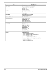
VGA Adapter Item Speaker LAN Adapter Wireless LAN Adapter Fax/Modem Adapter Power Supply Housing Specifications LEADTEK Geforce 2 MX-400 64M LP Prolink Geforce 2 MX-400 64M LP ECS SiS 315E ECS SiS 315E LB Charming Standard V-1 Charming Speake 2.1 ... FSP 180W non PFC FSP 160W PFC FSP 160W non PFC API 200W PFC API 200W non PFC Acer Genesis H80F Genesis H80 200W PFC (Delta) Genesis H80 200W non PFC (Delta, Hi-Power) Genesis H80 180W non PFC Genesis H40 200W PFC (Delta 200W only) Genesis H40 200W non PFC (Delta...
VGA Adapter Item Speaker LAN Adapter Wireless LAN Adapter Fax/Modem Adapter Power Supply Housing Specifications LEADTEK Geforce 2 MX-400 64M LP Prolink Geforce 2 MX-400 64M LP ECS SiS 315E ECS SiS 315E LB Charming Standard V-1 Charming Speake 2.1 ... FSP 180W non PFC FSP 160W PFC FSP 160W non PFC API 200W PFC API 200W non PFC Acer Genesis H80F Genesis H80 200W PFC (Delta) Genesis H80 200W non PFC (Delta, Hi-Power) Genesis H80 180W non PFC Genesis H40 200W PFC (Delta 200W only) Genesis H40 200W non PFC (Delta...


