
Veriton 3500G
Page 8
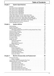
...Connecting peripherals 31 Connecting your mouse 31 Connecting your keyboard 34 Connecting a monitor 36 Connecting the power cable 37 Turning on your computer 38 Turning off your computer 39 Connecting options 40 Connecting your printer 40 Connecting the modem 41 Connecting to the network 42 Connecting multimedia devices 43 Connecting USB devices 46 4 Upgrading your computer 49 Installation precautions 51 ESD precautions 51 Preinstallation instructions 51 Post-installation instructions 52 Opening your computer 53 To remove the computer cover 53 To replace...
...Connecting peripherals 31 Connecting your mouse 31 Connecting your keyboard 34 Connecting a monitor 36 Connecting the power cable 37 Turning on your computer 38 Turning off your computer 39 Connecting options 40 Connecting your printer 40 Connecting the modem 41 Connecting to the network 42 Connecting multimedia devices 43 Connecting USB devices 46 4 Upgrading your computer 49 Installation precautions 51 ESD precautions 51 Preinstallation instructions 51 Post-installation instructions 52 Opening your computer 53 To remove the computer cover 53 To replace...
Veriton 3500G
Page 15
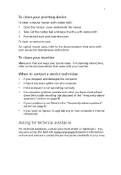
... your mouse for maintenance instructions. To clean your monitor Make sure that you want to contact the service centers available in the "Frequently-asked questions" section on page 81 • If your problem is not listed in your area. You may also access the Web site (www.acersupport.com) for technical assistance For technical assistance, contact your monitor. To clean an optical mouse: For optical mouse users, refer...
... your mouse for maintenance instructions. To clean your monitor Make sure that you want to contact the service centers available in the "Frequently-asked questions" section on page 81 • If your problem is not listed in your area. You may also access the Web site (www.acersupport.com) for technical assistance For technical assistance, contact your monitor. To clean an optical mouse: For optical mouse users, refer...

Veriton 3500G
Page 19
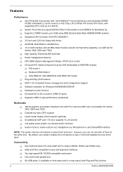
...; Intel Pentium® 4 processor • System memory expandable to a maximum of 1GB. • Power management function • 3.5-inch floppy drive • DVD-ROM, CD-ROM or CD-RW drive • High-capacity, Enhanced-IDE hard disk • Supports USB 2.0 high-performance peripherals Multimedia • 128-bit graphics accelerator installed in the AGP card slot • 3-D quality audio system via onboard audio controller • Audio-in/Line-in, Audio-out/Line-out, Headphone...
...; Intel Pentium® 4 processor • System memory expandable to a maximum of 1GB. • Power management function • 3.5-inch floppy drive • DVD-ROM, CD-ROM or CD-RW drive • High-capacity, Enhanced-IDE hard disk • Supports USB 2.0 high-performance peripherals Multimedia • 128-bit graphics accelerator installed in the AGP card slot • 3-D quality audio system via onboard audio controller • Audio-in/Line-in, Audio-out/Line-out, Headphone...
Veriton 3500G
Page 61
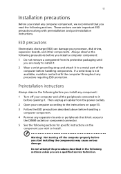
...! Not turning off your computer and all cables from its protective packaging until you are a qualified service technician. If a wrist strap is not available, maintain contact with preinstallation and post-installation instructions. Then unplug all the peripherals connected to a metal part of the computer before you install a computer component: 1 Do not remove a component from the power outlets. 2 Open your processor, disk drives, expansion boards, and...
...! Not turning off your computer and all cables from its protective packaging until you are a qualified service technician. If a wrist strap is not available, maintain contact with preinstallation and post-installation instructions. Then unplug all the peripherals connected to a metal part of the computer before you install a computer component: 1 Do not remove a component from the power outlets. 2 Open your processor, disk drives, expansion boards, and...

Veriton 3500G
Page 69
... CN9 CN10 CN11 CN12 CN13 CN14 CN16 CN17 CN18 CN19 CN20 CN21 CN22 CN23 59 Component Battery PS/2 mouse (upper) and keyboard (lower) ports USB ports COM 2 connector Game port Power connector Parallel (upper), serial (left) and monitor (right) ports FDD connector Network (upper) and USB (lower) ports Power connector (12V power) IDE 2 connector IDE 1 connector Line-out (top), line-in (middle), and rear microphonein (bottom) ports Audio FPIO connector CD-in connector Front USB 2.0 connector LAN active LED connector HDD LED connector Power button Intrusion connector Serial IRQ connector
... CN9 CN10 CN11 CN12 CN13 CN14 CN16 CN17 CN18 CN19 CN20 CN21 CN22 CN23 59 Component Battery PS/2 mouse (upper) and keyboard (lower) ports USB ports COM 2 connector Game port Power connector Parallel (upper), serial (left) and monitor (right) ports FDD connector Network (upper) and USB (lower) ports Power connector (12V power) IDE 2 connector IDE 1 connector Line-out (top), line-in (middle), and rear microphonein (bottom) ports Audio FPIO connector CD-in connector Front USB 2.0 connector LAN active LED connector HDD LED connector Power button Intrusion connector Serial IRQ connector

Veriton 3500G
Page 98
... 27 chair 27 connecting peripherals external monitor 36 power cable 37 USB keyboard 34 USB mouse 31 keyboard 30 monitor 30 mouse 30 system boards 56 audio board 61 mainboard 56, 57, 58 system utilities Acrobat Reader 74 LDCM 75 Norton AntiVirus 76 NTI CD-Maker 77 PowerDVD 78 reinstalling programs 80 T turning off computer 39 Index software shutdown 39 suspend mode 39 turning on computer 38 power button 38 U upgrade add memory 62 install DDR DIMM...
... 27 chair 27 connecting peripherals external monitor 36 power cable 37 USB keyboard 34 USB mouse 31 keyboard 30 monitor 30 mouse 30 system boards 56 audio board 61 mainboard 56, 57, 58 system utilities Acrobat Reader 74 LDCM 75 Norton AntiVirus 76 NTI CD-Maker 77 PowerDVD 78 reinstalling programs 80 T turning off computer 39 Index software shutdown 39 suspend mode 39 turning on computer 38 power button 38 U upgrade add memory 62 install DDR DIMM...
Veriton 3500G/5500G/7500G Service Guide
Page 7
... Password 58 Load Default Settings 59 Exiting Setup 60 Advanced Options 61 Product Information 61 Advanced BIOS Features 62 Advanced Chipset Features 63 Integrated Peripherals 64 Power Management Setup 65 Frequency Control 67 Chapter 3 Machine Disassembly and Replacement 69 General Information 70 Before You Begin 70 Veriton 3500/ 3500G Disassembly Flow Chart 71 Disassembling the Veriton 3500/ 3500G 72 Opening the Housing 72 Removing the Front Panel 73 Removing the AGP VGA Card 73 Removing the LAN Card...
... Password 58 Load Default Settings 59 Exiting Setup 60 Advanced Options 61 Product Information 61 Advanced BIOS Features 62 Advanced Chipset Features 63 Integrated Peripherals 64 Power Management Setup 65 Frequency Control 67 Chapter 3 Machine Disassembly and Replacement 69 General Information 70 Before You Begin 70 Veriton 3500/ 3500G Disassembly Flow Chart 71 Disassembling the Veriton 3500/ 3500G 72 Opening the Housing 72 Removing the Front Panel 73 Removing the AGP VGA Card 73 Removing the LAN Card...
Veriton 3500G/5500G/7500G Service Guide
Page 8
... Removing the Modem Card 99 Removing the AGP VGA Card 99 Removing the USB/ Audio Board 100 Removing the DVD-ROM and CD-RW Drive 101 Removing the Floppy Disk Drive 102 Removing the Hard Disk Drive 103 Removing the Intrusion Alarm Cable Module 103 Removing a DIMM 104 Removing the CPU Fan Sink 104 Removing and Installing the Processor 105 Removing and Installing the RTC Battery 105 Removing the Power Supply 106 Removing the LED Activity Indicators With Power Switch Cable Module .106 Removing the Main Board 107 Removing the I/O Port Bracket 107 Chapter 4 Troubleshooting...
... Removing the Modem Card 99 Removing the AGP VGA Card 99 Removing the USB/ Audio Board 100 Removing the DVD-ROM and CD-RW Drive 101 Removing the Floppy Disk Drive 102 Removing the Hard Disk Drive 103 Removing the Intrusion Alarm Cable Module 103 Removing a DIMM 104 Removing the CPU Fan Sink 104 Removing and Installing the Processor 105 Removing and Installing the RTC Battery 105 Removing the Power Supply 106 Removing the LED Activity Indicators With Power Switch Cable Module .106 Removing the Main Board 107 Removing the I/O Port Bracket 107 Chapter 4 Troubleshooting...
Veriton 3500G/5500G/7500G Service Guide
Page 12
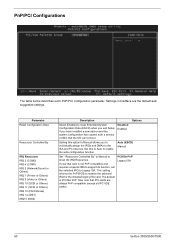
... AGP card 1.5V slot, supports 1X, 2X and 4X ! 3-D quality audio system via onboard audio controller ! Connectivity ! Supports 2 DIMM sockets up to 2.4GHz+. ! High capacity, Enhanced-IDE hard disk ! USB and PS/2 compatible mouse and keyboard interfaces ! Two high-speed NS 16C550-compatible serial ports ! Supports USB 2.0 high-performance peripherals Multimedia ! 128-bit graphics accelerator installed in the AGP Pro card slot (AGP slot: not available for Brookdale GL. ! By default, your system enables the...
... AGP card 1.5V slot, supports 1X, 2X and 4X ! 3-D quality audio system via onboard audio controller ! Connectivity ! Supports 2 DIMM sockets up to 2.4GHz+. ! High capacity, Enhanced-IDE hard disk ! USB and PS/2 compatible mouse and keyboard interfaces ! Two high-speed NS 16C550-compatible serial ports ! Supports USB 2.0 high-performance peripherals Multimedia ! 128-bit graphics accelerator installed in the AGP Pro card slot (AGP slot: not available for Brookdale GL. ! By default, your system enables the...

Veriton 3500G/5500G/7500G Service Guide
Page 37
...) +/- 10% DVD-ROM Interface Item Vendor & Model Name Performance Specification Transfer rate (KB/sec) Average access time Data Buffer Capacity Interface Pioneer DVD-117RD With CD Diskette Sustained: Max 3.6 MB/s 120ms 512 KBytes IDE/ATAPI Specification With DVD Diskette Sustained: Max8.31MB/s 180ms Chapter 1 27 Floppy disk drive Interface Item MTBF (Mean Time Between Failure) Floppy disk drive controller Floppy disk drive controller resident bus Support FDD format...
...) +/- 10% DVD-ROM Interface Item Vendor & Model Name Performance Specification Transfer rate (KB/sec) Average access time Data Buffer Capacity Interface Pioneer DVD-117RD With CD Diskette Sustained: Max 3.6 MB/s 120ms 512 KBytes IDE/ATAPI Specification With DVD Diskette Sustained: Max8.31MB/s 180ms Chapter 1 27 Floppy disk drive Interface Item MTBF (Mean Time Between Failure) Floppy disk drive controller Floppy disk drive controller resident bus Support FDD format...

Veriton 3500G/5500G/7500G Service Guide
Page 55
... Disabled if you enable or disable the USB keyboard driver within the onboard BIOS. Change the setting to your floppy disk drives to use a separate controller card. The PIO mode specifies the data transfer rate of the IDE cable. This item lets you want to the onboard floppy disk connector instead of a separate controller card. Most IDE drives, except with old designs, can support this parameter to the endmost connector of the HDD. The options...
... Disabled if you enable or disable the USB keyboard driver within the onboard BIOS. Change the setting to your floppy disk drives to use a separate controller card. The PIO mode specifies the data transfer rate of the IDE cable. This item lets you want to the onboard floppy disk connector instead of a separate controller card. Most IDE drives, except with old designs, can support this parameter to the endmost connector of the HDD. The options...

Veriton 3500G/5500G/7500G Service Guide
Page 58
... power switch is only used to Hard Drive, and it is set the default parameters for power-saving modes. Off - System would remain off the power management function. Enabled Disabled 48 Veriton 3500/5500/7500 This function allows you specify the IDE HDD idle time before the device enters the power down state. Set it to User Define to "Yes", then the VGA BIOS initiates automatically. When Delay 4 sec. Use this option to RAM) mode. Use PCI PME# Wake...
... power switch is only used to Hard Drive, and it is set the default parameters for power-saving modes. Off - System would remain off the power management function. Enabled Disabled 48 Veriton 3500/5500/7500 This function allows you specify the IDE HDD idle time before the device enters the power down state. Set it to User Define to "Yes", then the VGA BIOS initiates automatically. When Delay 4 sec. Use this option to RAM) mode. Use PCI PME# Wake...
Veriton 3500G/5500G/7500G Service Guide
Page 60
... IRQ Resources. If your ISA card is PCI/ISA PnP. Disabled Enabled Options Auto (ESCD) Manual PCI/ISA PnP Legacy ISA 50 Veriton 3500/5500/7500 Settings in boldface are always PnP compatible (except old PCI IDE cards). Parameter Reset Configuration Data Resources Controlled By IRQ Resources IRQ 3 (COM2) IRQ 4 (COM1) IRQ 5 (Network/Sound or Others) IRQ 7 (Printer or Others) IRQ 9 (Video or Others) IRQ 10 (SCSI...
... IRQ Resources. If your ISA card is PCI/ISA PnP. Disabled Enabled Options Auto (ESCD) Manual PCI/ISA PnP Legacy ISA 50 Veriton 3500/5500/7500 Settings in boldface are always PnP compatible (except old PCI IDE cards). Parameter Reset Configuration Data Resources Controlled By IRQ Resources IRQ 3 (COM2) IRQ 4 (COM1) IRQ 5 (Network/Sound or Others) IRQ 7 (Printer or Others) IRQ 9 (Video or Others) IRQ 10 (SCSI...

Veriton 3500G/5500G/7500G Service Guide
Page 74
... AGP card. . Video RAM Cacheable A.B segment shadow RAM cacheable. On-Chip Video Window size Aperture size for AGP card. The default setting by your DRAM's SPD. Parameter DRAM Timing Selectable Description SDRAM Timing By SPD Manual Option CAS Latency Time Active to Precharge Delay DRAM RAS #to decide how many size for on card. Memory Frequency for internal register, FWH, and LPC I/F accesses. The default setting by...
... AGP card. . Video RAM Cacheable A.B segment shadow RAM cacheable. On-Chip Video Window size Aperture size for AGP card. The default setting by your DRAM's SPD. Parameter DRAM Timing Selectable Description SDRAM Timing By SPD Manual Option CAS Latency Time Active to Precharge Delay DRAM RAS #to decide how many size for on card. Memory Frequency for internal register, FWH, and LPC I/F accesses. The default setting by...
Veriton 3500G/5500G/7500G Service Guide
Page 126
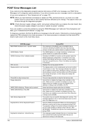
.... Some hard drives require extra time to replace the BIOS. NOTE: Check all power supply voltages, switch, and jumper settings before you replace the main board. This message usually indicates that no floppy drives are pressed during POST. Checksum of CPU. A weak battery may press Esc to "Undetermined Problems" on the keyboard. Make sure the controller is installed correctly, if no other activity has been affected by using the "BIOS Messages List...
.... Some hard drives require extra time to replace the BIOS. NOTE: Check all power supply voltages, switch, and jumper settings before you replace the main board. This message usually indicates that no floppy drives are pressed during POST. Checksum of CPU. A weak battery may press Esc to "Undetermined Problems" on the keyboard. Make sure the controller is installed correctly, if no other activity has been affected by using the "BIOS Messages List...
Veriton 3500G/5500G/7500G Service Guide
Page 127
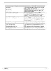
... own proprietary display. System OEMs may replace the Phoenix Technologies Award BIOS POST display with a set of the memory error. Including this message in the OEM display permits the operator to show POST screen Primary master hard disk fail Primary slave hard disk fail Secondary master hard disk fail Secondary slave hard disk fail Action/FRU This message displays during memory testing, additional information appears giving specifics about the type and location of BIOS defaults designed...
... own proprietary display. System OEMs may replace the Phoenix Technologies Award BIOS POST display with a set of the memory error. Including this message in the OEM display permits the operator to show POST screen Primary master hard disk fail Primary slave hard disk fail Secondary master hard disk fail Secondary slave hard disk fail Action/FRU This message displays during memory testing, additional information appears giving specifics about the type and location of BIOS defaults designed...

Veriton 3500G/5500G/7500G Service Guide
Page 129
... to master connector or the drive is set correctly and its eject button is configured correctly in BIOS Setup, cable/jumper are displayed. 1. Diskette drive power 3. Diskette drive 3. Main board Hard Disk Drive NOTE: Ensure hard disk drive is pressed and held. 1. Hard disk drive. 4. Enter BIOS Setup and Load default settings. 2. Hard disk drive LED fails to reinstall disc. Hard drive LED cable. Software asks to light, but system operates normally. 1. CD/DVD-ROM drive cannot load or eject when the system is turned on and its laser beam is connected to access for more...
... to master connector or the drive is set correctly and its eject button is configured correctly in BIOS Setup, cable/jumper are displayed. 1. Diskette drive power 3. Diskette drive 3. Main board Hard Disk Drive NOTE: Ensure hard disk drive is pressed and held. 1. Hard disk drive. 4. Enter BIOS Setup and Load default settings. 2. Hard disk drive LED fails to reinstall disc. Hard drive LED cable. Software asks to light, but system operates normally. 1. CD/DVD-ROM drive cannot load or eject when the system is turned on and its laser beam is connected to access for more...
Veriton 3500G/5500G/7500G Service Guide
Page 130
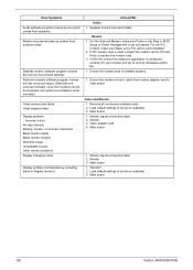
... configured correctly for your modem and set to Enabled. Remove all non-factory-installed cards. 2. Monitor 3. Monitor 3. "Monitor". 2. voice from modem adapter card to PCI slot firmly or replace the modem card. 3. Display problem: - Main board 1. Modem 1. Ensure the modem card is used, reinsert the modem card to main board Video and Monitor 1. For the PCI modem, make sure Power on By Ring in cable from modem cannot be produced, but system sound feature works normally.) Video memory test failed. Load default settings (if screen is readable). 3. Video adapter...
... configured correctly for your modem and set to Enabled. Remove all non-factory-installed cards. 2. Monitor 3. Monitor 3. "Monitor". 2. voice from modem adapter card to PCI slot firmly or replace the modem card. 3. Display problem: - Main board 1. Modem 1. Ensure the modem card is used, reinsert the modem card to main board Video and Monitor 1. For the PCI modem, make sure Power on By Ring in cable from modem cannot be produced, but system sound feature works normally.) Video memory test failed. Load default settings (if screen is readable). 3. Video adapter...
Veriton 3500G/5500G/7500G Service Guide
Page 131
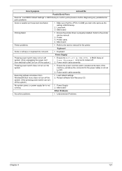
.../Serial Ports Execute "Load BIOS Default Settings" in BIOS Setup to the service manual for the power cable) is properly installed. Loop-back. 3. Printing failed. 1. Printer cable. 4. Power Supply 2. Make sure that the LPT# or COM# you test is not running. 1. Keyboard Some or all keys on the system. 1. Ensure the power override switch (situated at the back of Power Management is not set to the printer service manual. 2. No system power, or power supply fan is the same as the setting...
.../Serial Ports Execute "Load BIOS Default Settings" in BIOS Setup to the service manual for the power cable) is properly installed. Loop-back. 3. Printing failed. 1. Printer cable. 4. Power Supply 2. Make sure that the LPT# or COM# you test is not running. 1. Keyboard Some or all keys on the system. 1. Ensure the power override switch (situated at the back of Power Management is not set to the printer service manual. 2. No system power, or power supply fan is the same as the setting...
Veriton 3500G/5500G/7500G Service Guide
Page 174
... main board ID 37 product name 37 system BIOS version 37 system serial number 37 PS/2 keyboard port 11, 14 PS/2 mouse port 10, 14 R Removal and Replacement 69 removing 88, 90, 105 Replacement Assembly, Machine 69 replacing HDD 91 RIMM Removing 80, 103 RMA 127 Routing Map 30 S Security 55 Serial Port 29 Serial port 10, 15 socket memory 24 Socket 370 23 Suspend Mode 34 Switching Power Supply 102W 32 Symptoms List 164 Veriton 3500...
... main board ID 37 product name 37 system BIOS version 37 system serial number 37 PS/2 keyboard port 11, 14 PS/2 mouse port 10, 14 R Removal and Replacement 69 removing 88, 90, 105 Replacement Assembly, Machine 69 replacing HDD 91 RIMM Removing 80, 103 RMA 127 Routing Map 30 S Security 55 Serial Port 29 Serial port 10, 15 socket memory 24 Socket 370 23 Suspend Mode 34 Switching Power Supply 102W 32 Symptoms List 164 Veriton 3500...


