TravelMate 6492/6492G User's Guide EN
Page 5
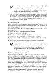
... performance of the battery, charging will not occur at temperatures below 0°C (32°F) or above 40°C (104°F). Do not pierce, open or disassemble the battery.
... performance of the battery, charging will not occur at temperatures below 0°C (32°F) or above 40°C (104°F). Do not pierce, open or disassemble the battery.
TravelMate 6492/6492G User's Guide EN
Page 6
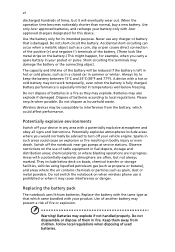
...of used batteries. Wireless devices may explode. Warning! Please recycle when possible. Switch off your pocket or purse. Use only Acer approved batteries, and recharge your vehicle engine. Follow local regulations when disposing of batteries in progress. Observe restrictions on the use...you would normally be susceptible to interference from children. Dispose of radio equipment in bodily injury or even death. Do not disassemble or dispose of fire or explosion. Use of another battery may explode if not handled properly. Always try to local ...
...of used batteries. Wireless devices may explode. Warning! Please recycle when possible. Switch off your pocket or purse. Use only Acer approved batteries, and recharge your vehicle engine. Follow local regulations when disposing of batteries in progress. Observe restrictions on the use...you would normally be susceptible to interference from children. Dispose of radio equipment in bodily injury or even death. Do not disassemble or dispose of fire or explosion. Use of another battery may explode if not handled properly. Always try to local ...
TravelMate 6492/6492G User's Guide EN
Page 87
... A LASER DE CLASSE 1 PRODUIT LASERATTENTION: RADIATION DU FAISCEAU LASER INVISIBLE EN CAS D'OUVERTURE. Use of this computer is prohibited. and 6,516,132." Reverse engineering or disassembly is a laser product. LUOKAN 1 LASERLAITE LASER KLASSE 1 VORSICHT: UNSICHTBARE LASERSTRAHLUNG, WENN ABDECKUNG GEÖFFNET NICHT DEM STRAHLL AUSSETZEN PRODUCTO LÁSER DE LA CLASE...
... A LASER DE CLASSE 1 PRODUIT LASERATTENTION: RADIATION DU FAISCEAU LASER INVISIBLE EN CAS D'OUVERTURE. Use of this computer is prohibited. and 6,516,132." Reverse engineering or disassembly is a laser product. LUOKAN 1 LASERLAITE LASER KLASSE 1 VORSICHT: UNSICHTBARE LASERSTRAHLUNG, WENN ABDECKUNG GEÖFFNET NICHT DEM STRAHLL AUSSETZEN PRODUCTO LÁSER DE LA CLASE...

Service Guide
Page 8
...57 Exit ...58 BIOS Flash Utility 59 Chapter 3 Machine Disassembly and Replacement 61 General Information 61 Before You Begin 61 Disassembly Procedure Flowcharts 62 Main Unit Disassembly Flowchart 62 LCM Module Disassembly Flowchart 63 Main Unit Disassembly Procedure 64 Removing the Battery Pack 64 Removing the CTO Cover... Removing the TouchPad 74 Removing the Mainboard 74 Removing the Heatsink and Fan Module 76 Removing the CPU 77 LCM Module Disassembly Procedure 78 Removing the LCM Bezel 78 Removing the LCD Panel 79 LCM Module Reassembly Procedure 82 Replacing the LCD Panel...
...57 Exit ...58 BIOS Flash Utility 59 Chapter 3 Machine Disassembly and Replacement 61 General Information 61 Before You Begin 61 Disassembly Procedure Flowcharts 62 Main Unit Disassembly Flowchart 62 LCM Module Disassembly Flowchart 63 Main Unit Disassembly Procedure 64 Removing the Battery Pack 64 Removing the CTO Cover... Removing the TouchPad 74 Removing the Mainboard 74 Removing the Heatsink and Fan Module 76 Removing the CPU 77 LCM Module Disassembly Procedure 78 Removing the LCM Bezel 78 Removing the LCD Panel 79 LCM Module Reassembly Procedure 82 Replacing the LCD Panel...

Service Guide
Page 71
...off the power to scrape the cover. Before You Begin Before proceeding with the corresponding components to disassemble the notebook computer for the different components vary in size. To disassemble the computer, you remove the stripe cover, please be careful not to the system and all... power and signal cables from the system. Chapter 3 61 Chapter 3 Machine Disassembly and Replacement General Information This chapter contains step...
...off the power to scrape the cover. Before You Begin Before proceeding with the corresponding components to disassemble the notebook computer for the different components vary in size. To disassemble the computer, you remove the stripe cover, please be careful not to the system and all... power and signal cables from the system. Chapter 3 61 Chapter 3 Machine Disassembly and Replacement General Information This chapter contains step...

Service Guide
Page 72
Main Unit Disassembly Flowchart 62 Chapter 3 For example, if you must first remove the keyboard, then disassemble the inside assembly frame in that order. Disassembly Procedure Flowcharts The following flowcharts give you a graphic representation on the entire disassembly sequence and instructs you on the components that need to remove the system board, you want to be removed during servicing.
Main Unit Disassembly Flowchart 62 Chapter 3 For example, if you must first remove the keyboard, then disassemble the inside assembly frame in that order. Disassembly Procedure Flowcharts The following flowcharts give you a graphic representation on the entire disassembly sequence and instructs you on the components that need to remove the system board, you want to be removed during servicing.

Service Guide
Page 74
Remove the battery. Removing the CTO Cover 1. Main Unit Disassembly Procedure Removing the Battery Pack 1. Turn the computer over. Lift to remove the screws 3. Push and hold release latch. 3. Locate and loosen the seven screws as shown. Lift the CTO cover using the indented top edge as shown. 2. from chassis. Release the battery locks as shown. 2. Note: It is not necessary to 45° angle and remove from the CTO Cover. 64 Chapter 3
Remove the battery. Removing the CTO Cover 1. Main Unit Disassembly Procedure Removing the Battery Pack 1. Turn the computer over. Lift to remove the screws 3. Push and hold release latch. 3. Locate and loosen the seven screws as shown. Lift the CTO cover using the indented top edge as shown. 2. from chassis. Release the battery locks as shown. 2. Note: It is not necessary to 45° angle and remove from the CTO Cover. 64 Chapter 3

Service Guide
Page 88
Locate and remove the four mylar (small red markers) and two rubber (large red markers) screw covers as shown. 3. Remove the bezel from the LCM Module. LCM Module Disassembly Procedure Removing the LCM Bezel CAUTION: When using tools, be careful not to pass 4. they are reusable. 2. Remove the six bezel securing screws. Push in the cover locks to allow the bezel to scratch the computer casing. 1. Loosen the bezel by lifting all the edges upward as shown. freely over them. 78 Chapter 3 Note: Do not discard the screw covers -
Locate and remove the four mylar (small red markers) and two rubber (large red markers) screw covers as shown. 3. Remove the bezel from the LCM Module. LCM Module Disassembly Procedure Removing the LCM Bezel CAUTION: When using tools, be careful not to pass 4. they are reusable. 2. Remove the six bezel securing screws. Push in the cover locks to allow the bezel to scratch the computer casing. 1. Loosen the bezel by lifting all the edges upward as shown. freely over them. 78 Chapter 3 Note: Do not discard the screw covers -


