

TravelMate 630 Service Guide
Page 8
...60 Removing the Hard Disk Drive Module 61 Disassembling the Main Unit 62 Removing the Middle Cover 62 Removing the Keyboard 62 Removing the LCD Module 63 Removing the RTC Battery 64 Removing the MINI PCI Plate 64 Removing the CPU Heat Sink 64 Removing the CPU 65 Separating...Removing the PCMCIA Socket 69 Removing the Modem Cable 70 Disassembling the LCD Module 71 Removing the LCD Bezel 71 Removing the LCD Hinges 71 Removing the LCD Latch 72 Removing the Inverter Board 72 Removing the LCD 72 Removing the LCD Brackets 73 Removing the Coaxial Cable 74 System Upgrade Procedure 75 ...
...60 Removing the Hard Disk Drive Module 61 Disassembling the Main Unit 62 Removing the Middle Cover 62 Removing the Keyboard 62 Removing the LCD Module 63 Removing the RTC Battery 64 Removing the MINI PCI Plate 64 Removing the CPU Heat Sink 64 Removing the CPU 65 Separating...Removing the PCMCIA Socket 69 Removing the Modem Cable 70 Disassembling the LCD Module 71 Removing the LCD Bezel 71 Removing the LCD Hinges 71 Removing the LCD Latch 72 Removing the Inverter Board 72 Removing the LCD 72 Removing the LCD Brackets 73 Removing the Coaxial Cable 74 System Upgrade Procedure 75 ...

TravelMate 630 Service Guide
Page 11
... ! ! ! ! ! ! Internal removable optical drive (removable CD or DVD drive) ! Thin-Film Transistor (TFT) liquid crystal-display (LCD) displaying 16-bit high color up to a television or display device that automatically decides the best settings for output to 1GB ! Smart Card interface... extended Graphics Array+ (XGA) resolution for 14.1" and 1400X1050 Super extended Graphics Array+ (SXGA+) resolution for 15". 3D capabilities Simultaneous LCD and CRT display support S-video for your display and conserves power Dual display capability Multimedia ! ! ! ! 16-bit high-fidelity AC...
... ! ! ! ! ! ! Internal removable optical drive (removable CD or DVD drive) ! Thin-Film Transistor (TFT) liquid crystal-display (LCD) displaying 16-bit high color up to a television or display device that automatically decides the best settings for output to 1GB ! Smart Card interface... extended Graphics Array+ (XGA) resolution for 14.1" and 1400X1050 Super extended Graphics Array+ (SXGA+) resolution for 15". 3D capabilities Simultaneous LCD and CRT display support S-video for your display and conserves power Dual display capability Multimedia ! ! ! ! 16-bit high-fidelity AC...

TravelMate 630 Service Guide
Page 13
System Block Diagram DDR BUFFER CPU Northwood-m uFCPGA CLK GEN ICS 951104 2M * 32BIT * 4Bank *4 CRT LVDS LCD VGA NVIDIA GEFORCE2GO 100 AGP 4x 1.5 v 66 MHz TV OUT TV ENCODER CH7007 1394 VT6306L CARDBUS 711 PCI BUS 33MHz MiniPCi 802.11b ATA 66 / ...
System Block Diagram DDR BUFFER CPU Northwood-m uFCPGA CLK GEN ICS 951104 2M * 32BIT * 4Bank *4 CRT LVDS LCD VGA NVIDIA GEFORCE2GO 100 AGP 4x 1.5 v 66 MHz TV OUT TV ENCODER CH7007 1394 VT6306L CARDBUS 711 PCI BUS 33MHz MiniPCi 802.11b ATA 66 / ...

TravelMate 630 Service Guide
Page 16
Front View # Icon Item Description 1 Display screen Also called LCD (liquid-crystal display), diplays computer output. 2 Status indicators LEDs (light-emitting diode) that turn on and off to show the status of ports allow you ...
Front View # Icon Item Description 1 Display screen Also called LCD (liquid-crystal display), diplays computer output. 2 Status indicators LEDs (light-emitting diode) that turn on and off to show the status of ports allow you ...

TravelMate 630 Service Guide
Page 19
....7 million colors at 1400x1050 resolution. 5 Easy Link Port/ Replicator I/O replicator for EasyPort expansion devices. video input. 4 External display port Connects to a display device (e.g., external monitor, LCD projector) and displays up to IEEE 1394 devices. Rear Panel # Icon Item Description 1 Power jack Connects to an AC adapter 2 USB ports (two) Connect to...
....7 million colors at 1400x1050 resolution. 5 Easy Link Port/ Replicator I/O replicator for EasyPort expansion devices. video input. 4 External display port Connects to a display device (e.g., external monitor, LCD projector) and displays up to IEEE 1394 devices. Rear Panel # Icon Item Description 1 Power jack Connects to an AC adapter 2 USB ports (two) Connect to...

TravelMate 630 Service Guide
Page 33
... 1 IRQ3, IRQ5, IRQ7, IRQ9, IRQ10, IRQ11 Video Interface Item Chip vendor and model name Chip voltage Supports ZV (Zoomed Video) port Graph interface Maximum resolution (LCD) Maximum resolution (CRT) Specification NVIDIA GeforceGO 100 Core/2.5V Memory/2.5V No 4X AGP (Accelerated Graphics Port) bus 1600x12000 (32 bit colors) 1920x1200(32 bit...
... 1 IRQ3, IRQ5, IRQ7, IRQ9, IRQ10, IRQ11 Video Interface Item Chip vendor and model name Chip voltage Supports ZV (Zoomed Video) port Graph interface Maximum resolution (LCD) Maximum resolution (CRT) Specification NVIDIA GeforceGO 100 Core/2.5V Memory/2.5V No 4X AGP (Accelerated Graphics Port) bus 1600x12000 (32 bit colors) 1920x1200(32 bit...

TravelMate 630 Service Guide
Page 34
Video Resolutions Mode (for both LCD and CRT) Resolution 640x480 720x480 800x600 848x480 1024x768 1152x864 1280x1024 1400x1050 1600x1200 8 bits (256 colors) Yes Yes Yes Yes Yes Yes Yes Yes Yes 16 ...
Video Resolutions Mode (for both LCD and CRT) Resolution 640x480 720x480 800x600 848x480 1024x768 1152x864 1280x1024 1400x1050 1600x1200 8 bits (256 colors) Yes Yes Yes Yes Yes Yes Yes Yes Yes 16 ...
TravelMate 630 Service Guide
Page 36
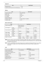
...: DC-AC inverter is used to generate very high AC voltage, then support to update the ID information. LCD Item Vendor & model name Mechanical Specifications LCD display area (diagonal, inch) Display technology Resolution Supports colors Optical Specification Brightness control 26 AU B150PG01 Specification AU ... TFT XGA (1024X768) 262K keyboard hotkey Keyboard hotkey Chapter 1 If you replace a new inverter or replace the LCD with a different brand, use Inverter ID utility to LCD CCFT backlight user, and is turned on. Avoid touching the DC-AC inverter area while the system unit is...
...: DC-AC inverter is used to generate very high AC voltage, then support to update the ID information. LCD Item Vendor & model name Mechanical Specifications LCD display area (diagonal, inch) Display technology Resolution Supports colors Optical Specification Brightness control 26 AU B150PG01 Specification AU ... TFT XGA (1024X768) 262K keyboard hotkey Keyboard hotkey Chapter 1 If you replace a new inverter or replace the LCD with a different brand, use Inverter ID utility to LCD CCFT backlight user, and is turned on. Avoid touching the DC-AC inverter area while the system unit is...

TravelMate 630 Service Guide
Page 37
... 0.25 mA max. (@ 254 Vac, 60Hz) Internal filter meets: 1. CISPR 22 Class B requirements. (Scandinavia) 4. FCC class B requirements. (USA) 2. LCD Item Contrast control No Electrical Specification Supply voltage for LCD display (V) 3.3 Supply voltage for LCD backlight (Vrms) 700 Specification No 3.3 660 AC Adapter Item Vendor & model name Input Requirements Maximum input current (A, @90Vac, full...
... 0.25 mA max. (@ 254 Vac, 60Hz) Internal filter meets: 1. CISPR 22 Class B requirements. (Scandinavia) 4. FCC class B requirements. (USA) 2. LCD Item Contrast control No Electrical Specification Supply voltage for LCD display (V) 3.3 Supply voltage for LCD backlight (Vrms) 700 Specification No 3.3 660 AC Adapter Item Vendor & model name Input Requirements Maximum input current (A, @90Vac, full...

TravelMate 630 Service Guide
Page 44
...or Disable Help: Allow the system to Auto, the computer automatically determines the display device. This will support an automatic dim in of the LCD backlight when the AC power is connected, it becomes the boot display. Options: Enable or Disable Help: The system will decrease the time ...needed to both the LCD and the external display if one is connected. Parameter Boot Display Screen Expansion QuickBoot Mode Boot-time Diagnostic Screen Boot on LAN Hotkey Beep...
...or Disable Help: Allow the system to Auto, the computer automatically determines the display device. This will support an automatic dim in of the LCD backlight when the AC power is connected, it becomes the boot display. Options: Enable or Disable Help: The system will decrease the time ...needed to both the LCD and the external display if one is connected. Parameter Boot Display Screen Expansion QuickBoot Mode Boot-time Diagnostic Screen Boot on LAN Hotkey Beep...

TravelMate 630 Service Guide
Page 56
... Panel ID is not bootable, do the following functions: 1. Set Thermal Setting This function will display registered information on the panel ID of Acer TravelMate 630 series. First, the default of scrollbar (option item) will introduce each test utility and its functions. That is displayed. Default Setting The ...the screen.Otherwise, an error message is for three different ranges of mother board data. Read Thermal This function will write a default LCD panel ID into EEPROM. 2. Test Fan The test item includes fan off test then it is considered as Panel ID, Thermal Setting,...
... Panel ID is not bootable, do the following functions: 1. Set Thermal Setting This function will display registered information on the panel ID of Acer TravelMate 630 series. First, the default of scrollbar (option item) will introduce each test utility and its functions. That is displayed. Default Setting The ...the screen.Otherwise, an error message is for three different ranges of mother board data. Read Thermal This function will write a default LCD panel ID into EEPROM. 2. Test Fan The test item includes fan off test then it is considered as Panel ID, Thermal Setting,...

TravelMate 630 Service Guide
Page 65
... ROM Kit Covers Module HDD Module Hx1 HDD Ax2 Modem Board DIMM RTC Battery HDD Bracket MINI PCI Plate Kx4 Gx2 Lx1 Coaxial Cable Cx6 LCD Module (See Next Page) Cx6 CD/DVD ROM Drive Ix2 CD/DVD ROM Transfer Board CPU Fan Sink Two Antennas Upper Case Lower Case Gx4...
... ROM Kit Covers Module HDD Module Hx1 HDD Ax2 Modem Board DIMM RTC Battery HDD Bracket MINI PCI Plate Kx4 Gx2 Lx1 Coaxial Cable Cx6 LCD Module (See Next Page) Cx6 CD/DVD ROM Drive Ix2 CD/DVD ROM Transfer Board CPU Fan Sink Two Antennas Upper Case Lower Case Gx4...

TravelMate 630 Service Guide
Page 66
LCD Module Bx4 LCD Bezel Ox2 LCD HInges Inverter Board Dx4 LCD LCD Panel Gx6 LCD Brackets Coaxial Cable Screw List Item A B C D E F G H I J K L M N O Description Screw M2 X L4 (Black) Screw M2.5 X L6 (Black) Screw M2.5 X L8 ((Black) Screw M2 X L3.5 (Silver) Screw M2 X L5 (Black) Screw DIMM Cover Steel Nagana-1 (Black) Screw M2 X L3 (Silver) Screw M3x4 (Silver) CD-ROM SPECIAL SCREW HEX SCREW CPU HEAT SINK SPECIAL SCREW Screw M2x10 (Silver) Screw M2.5x5 (Silver) Screw M2x4 (Black) Screw M2.5x4 (Black) 56 LCD Latch Chapter 3
LCD Module Bx4 LCD Bezel Ox2 LCD HInges Inverter Board Dx4 LCD LCD Panel Gx6 LCD Brackets Coaxial Cable Screw List Item A B C D E F G H I J K L M N O Description Screw M2 X L4 (Black) Screw M2.5 X L6 (Black) Screw M2.5 X L8 ((Black) Screw M2 X L3.5 (Silver) Screw M2 X L5 (Black) Screw DIMM Cover Steel Nagana-1 (Black) Screw M2 X L3 (Silver) Screw M3x4 (Silver) CD-ROM SPECIAL SCREW HEX SCREW CPU HEAT SINK SPECIAL SCREW Screw M2x10 (Silver) Screw M2.5x5 (Silver) Screw M2x4 (Black) Screw M2.5x4 (Black) 56 LCD Latch Chapter 3

TravelMate 630 Service Guide
Page 73
See "Removing the Keyboard" on page 62 3. Remove the one screw as shown and then lift up the LCD module carefully. Remove the four screws as shown, disconnect the LCD coaxial cable and the LED/inverter cable from the main board. 5. Chapter 3 63 Removing the LCD Module 1. See "Removing the Middle Cover" on page 62 4. Release the two screws on page 57 2. See "Removing the Battery Pack" on the back side of the unit. 6.
See "Removing the Keyboard" on page 62 3. Remove the one screw as shown and then lift up the LCD module carefully. Remove the four screws as shown, disconnect the LCD coaxial cable and the LED/inverter cable from the main board. 5. Chapter 3 63 Removing the LCD Module 1. See "Removing the Middle Cover" on page 62 4. Release the two screws on page 57 2. See "Removing the Battery Pack" on the back side of the unit. 6.

TravelMate 630 Service Guide
Page 75
... PCI Plate" on page 62 3. Release the screw counter clockwise by using a flat screwdriver. 7. See "Removing the Battery Pack" on page 63 5. See "Removing the LCD Module" on page 57 2. Remove the CPU and then secure the screw clockwise to its socket, please put it back with the triangle mark this...
... PCI Plate" on page 62 3. Release the screw counter clockwise by using a flat screwdriver. 7. See "Removing the Battery Pack" on page 63 5. See "Removing the LCD Module" on page 57 2. Remove the CPU and then secure the screw clockwise to its socket, please put it back with the triangle mark this...

TravelMate 630 Service Guide
Page 76
... below and then remove the upper case from the upper case. 66 Chapter 3 See "Separating the Lower Case from the upper case. 8. See "Removing the LCD Module" on page 57 2. Removing the TouchPad Module 1. See "Removing the Battery Pack" on page 63 5. Snap off the touchpad frame from the upper case...
... below and then remove the upper case from the upper case. 66 Chapter 3 See "Separating the Lower Case from the upper case. 8. See "Removing the LCD Module" on page 57 2. Removing the TouchPad Module 1. See "Removing the Battery Pack" on page 63 5. Snap off the touchpad frame from the upper case...

TravelMate 630 Service Guide
Page 77
...from the Upper Case" on page 65 7. See "Separating the Lower Case from the daughter board. 8. Removing the Daughter Board 1. See "Removing the LCD Module" on the daughter board. 8. Disconnect the two speaker cables on page 63 5. See "Removing the Keyboard" on page 62 3. Remove the ...6. See "Removing the RTC Battery" on page 62 3. Removing the Speakers 1. See "Removing the Battery Pack" on page 63 5. See "Removing the LCD Module" on page 57 2. See "Removing the RTC Battery" on page 57 2. See "Separating the Lower Case from the lower case. See "Removing ...
...from the Upper Case" on page 65 7. See "Separating the Lower Case from the daughter board. 8. Removing the Daughter Board 1. See "Removing the LCD Module" on the daughter board. 8. Disconnect the two speaker cables on page 63 5. See "Removing the Keyboard" on page 62 3. Remove the ...6. See "Removing the RTC Battery" on page 62 3. Removing the Speakers 1. See "Removing the Battery Pack" on page 63 5. See "Removing the LCD Module" on page 57 2. See "Removing the RTC Battery" on page 57 2. See "Separating the Lower Case from the lower case. See "Removing ...

TravelMate 630 Service Guide
Page 78
See "Removing the Battery Pack" on page 57 2. See "Removing the Battery Pack" on page 57 2. See "Removing the LCD Module" on page 67 9. See "Removing the Daughter Board" on page 63 5. See "Removing the RTC Battery" on page 67 8. Removing I/O Port Chassis 1. See "... page 64 7. See "Removing the CPU Heat Sink" on page 62 3. See "Separating the Lower Case from the lower case with caution. See "Removing the LCD Module" on page 62 4. Removing the Main Board 1. See "Removing the Keyboard" on page 63 5. See "Removing the Middle Cover" on page 68 68 ...
See "Removing the Battery Pack" on page 57 2. See "Removing the Battery Pack" on page 57 2. See "Removing the LCD Module" on page 67 9. See "Removing the Daughter Board" on page 63 5. See "Removing the RTC Battery" on page 67 8. Removing I/O Port Chassis 1. See "... page 64 7. See "Removing the CPU Heat Sink" on page 62 3. See "Separating the Lower Case from the lower case with caution. See "Removing the LCD Module" on page 62 4. Removing the Main Board 1. See "Removing the Keyboard" on page 63 5. See "Removing the Middle Cover" on page 68 68 ...

TravelMate 630 Service Guide
Page 79
... Lower Case from the main board. See "Removing I /O port chassis. See "Removing the Main Board" on page 67 8. Removing the PCMCIA Socket 1. See "Removing the LCD Module" on page 64 6. Chapter 3 69 Remove the four hex screw as shown here, remove the PCMCIA cable from the main board, and then detach...
... Lower Case from the main board. See "Removing I /O port chassis. See "Removing the Main Board" on page 67 8. Removing the PCMCIA Socket 1. See "Removing the LCD Module" on page 64 6. Chapter 3 69 Remove the four hex screw as shown here, remove the PCMCIA cable from the main board, and then detach...

TravelMate 630 Service Guide
Page 80
See "Removing the Keyboard" on page 63 5. See "Removing the LCD Module" on page 62 4. Remove the tapes on page 57 2. See "Removing the Battery Pack" on the modem cable and disconnect the modem cable from the main board. 10. See "Separating the Lower Case from the main unit carefully. 70 Chapter 3 Remove the modem cable from the Upper Case" on page 70 9. See "Removing the Modem Cable" on page 65 7. See "Removing the Middle Cover" on page 67 8. See "Removing the Daughter Board" on page 62 3. See "Removing the RTC Battery" on page 64 6. Removing the Modem Cable 1.
See "Removing the Keyboard" on page 63 5. See "Removing the LCD Module" on page 62 4. Remove the tapes on page 57 2. See "Removing the Battery Pack" on the modem cable and disconnect the modem cable from the main board. 10. See "Separating the Lower Case from the main unit carefully. 70 Chapter 3 Remove the modem cable from the Upper Case" on page 70 9. See "Removing the Modem Cable" on page 65 7. See "Removing the Middle Cover" on page 67 8. See "Removing the Daughter Board" on page 62 3. See "Removing the RTC Battery" on page 64 6. Removing the Modem Cable 1.


