TravelMate 4060 Service Guide
Page 8
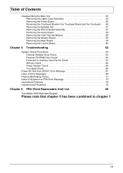
... 55 Removing the Upper Case Assembly 55 Removing the Power Board 55 Removing the Touchpad Bracket, the Touchpad Board and the Touchpad . . . .56 Removing the Speaker Set 57 Removing the SW DJ Board Assembly 57 Removing the Audio Board 58 Removing the VGA Thermal Module 58 Removing the Modem... Power System Check 64 Touchpad Check 66 Power-On Self-Test (POST) Error Message 67 Index of Error Messages 68 Phoenix BIOS Beep Codes 71 Index of Symptom-to-FRU Error Message 75 Intermittent Problems 78 Undetermined Problems 79 Chapter 6 FRU (Field Replaceable Unit) List 80 TravelMate 4060...
... 55 Removing the Upper Case Assembly 55 Removing the Power Board 55 Removing the Touchpad Bracket, the Touchpad Board and the Touchpad . . . .56 Removing the Speaker Set 57 Removing the SW DJ Board Assembly 57 Removing the Audio Board 58 Removing the VGA Thermal Module 58 Removing the Modem... Power System Check 64 Touchpad Check 66 Power-On Self-Test (POST) Error Message 67 Index of Error Messages 68 Phoenix BIOS Beep Codes 71 Index of Symptom-to-FRU Error Message 75 Intermittent Problems 78 Undetermined Problems 79 Chapter 6 FRU (Field Replaceable Unit) List 80 TravelMate 4060...
TravelMate 4060 Service Guide
Page 14
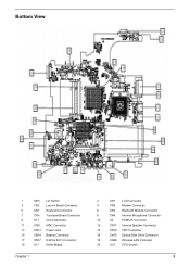
Bottom View 1 SW1 Lid Switch 3 CN2 Launch Board Connector 5 CN7 Keyboard Connector 7 CN5 Touchpad Board Connector 9 U17 Clock Generator 11 CN9 MDC Connector 13 CN13 Power Jack 15 CN14 Battery Connector 17 CN17 RJ45 & RJ11 Connector 19 U11 North Bridge Chapter 1 2 CN1 LCD Connector 4 CN3 Modem Connector 6 CN4 Bluetooth Module Connector 8 CN6 Internal Microphone Connector 10 U4 PCMCIA Connector 12 CN11 Internal Speaker Connector 14 CN12 CRT Connector 16 CN15 Optical Disk Drive Connector 18 CN26 Wireless LAN Controller 20 U13 CPU Socket 5
Bottom View 1 SW1 Lid Switch 3 CN2 Launch Board Connector 5 CN7 Keyboard Connector 7 CN5 Touchpad Board Connector 9 U17 Clock Generator 11 CN9 MDC Connector 13 CN13 Power Jack 15 CN14 Battery Connector 17 CN17 RJ45 & RJ11 Connector 19 U11 North Bridge Chapter 1 2 CN1 LCD Connector 4 CN3 Modem Connector 6 CN4 Bluetooth Module Connector 8 CN6 Internal Microphone Connector 10 U4 PCMCIA Connector 12 CN11 Internal Speaker Connector 14 CN12 CRT Connector 16 CN15 Optical Disk Drive Connector 18 CN26 Wireless LAN Controller 20 U13 CPU Socket 5
TravelMate 4060 Service Guide
Page 27
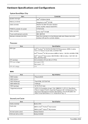
... SMBIOS 2.3, PCI 2.2, Boot Block, PXE 2.0, Mobile PC2001, Hard Disk Password, INT 13h Extensions, PCI Bus Power Management interface Specification, EI Torito-Bootable CDROM Format Specification V1.0, Simple Boot Flag 1.0 Second Level Cache Item Cache controller...174; Celeron® M processor Always Enabled Always Enabled 18 TravelMate 4060 Hardware Specifications and Configurations System Board Major Chip Item System core logic Memory controller Audio controller PCMCIA controller for socket Video controller Power and Keyboard controller Wireless controller (mini PCI) Controller Intel&#...
... SMBIOS 2.3, PCI 2.2, Boot Block, PXE 2.0, Mobile PC2001, Hard Disk Password, INT 13h Extensions, PCI Bus Power Management interface Specification, EI Torito-Bootable CDROM Format Specification V1.0, Simple Boot Flag 1.0 Second Level Cache Item Cache controller...174; Celeron® M processor Always Enabled Always Enabled 18 TravelMate 4060 Hardware Specifications and Configurations System Board Major Chip Item System core logic Memory controller Audio controller PCMCIA controller for socket Video controller Power and Keyboard controller Wireless controller (mini PCI) Controller Intel&#...
TravelMate 4060 Service Guide
Page 64
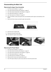
...5. See "Removing the Memory" on page 47. 3. Disconnect the touchpad cable. 9. Then detach the upper case assembly. Removing the Power Board 1. Tear off the tape holding the power board cable then remove the power board. 55 Chapter 3 Remove the three screws securing the upper case assembly. 8. Remove the two screws securing the... power board. 7. See "Removing the Battery" on page 50. 6. See "Removing the LCD Module" on page 46.. 2. See "Removing the Hard Disc Drive ...
...5. See "Removing the Memory" on page 47. 3. Disconnect the touchpad cable. 9. Then detach the upper case assembly. Removing the Power Board 1. Tear off the tape holding the power board cable then remove the power board. 55 Chapter 3 Remove the three screws securing the upper case assembly. 8. Remove the two screws securing the... power board. 7. See "Removing the Battery" on page 50. 6. See "Removing the LCD Module" on page 46.. 2. See "Removing the Hard Disc Drive ...
TravelMate 4060 Service Guide
Page 65
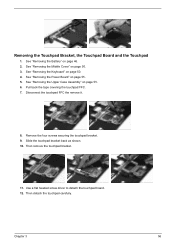
...the Upper Case Assembly" on page 55. 5. Slide the touchpad bracket back as shown. 10. Then detach the touchpad carefully. See "Removing the Power Board" on page 55. 6. Then remove the touchpad bracket. 11. Chapter 3 56 Pull back the tape covering the touchpad FFC. 7. Disconnect the...the remove it. 8. Remove the four screws securing the touchpad bracket. 9. Removing the Touchpad Bracket, the Touchpad Board and the Touchpad 1. Use a flat headed screw driver to detach the touchpad board. 12. See "Removing the Keyboard" on page 50. 3. See "Removing the Middle Cover" on page ...
...the Upper Case Assembly" on page 55. 5. Slide the touchpad bracket back as shown. 10. Then detach the touchpad carefully. See "Removing the Power Board" on page 55. 6. Then remove the touchpad bracket. 11. Chapter 3 56 Pull back the tape covering the touchpad FFC. 7. Disconnect the...the remove it. 8. Remove the four screws securing the touchpad bracket. 9. Removing the Touchpad Bracket, the Touchpad Board and the Touchpad 1. Use a flat headed screw driver to detach the touchpad board. 12. See "Removing the Keyboard" on page 50. 3. See "Removing the Middle Cover" on page ...

TravelMate 4060 Service Guide
Page 66
...55. 6. Disconnect the CIR receiver cable. 8. Removing the SW DJ Board Assembly 1. Remove the two screws securing the SW DJ board assembly. 57 Chapter 3 See "Removing the Upper Case Assembly" on page 50. 3. Disconnect the SW DJ board cable. 7. Disconnect the speaker set from the lower case. See "... Cover" on page 57. 7. See "Removing the Speaker Set" on page 50. 3. Then detach the speaker set cable. 10. See "Removing the Power Board" on page 50. 4. See "Removing the Keyboard" on page 55. 5. Removing the Speaker Set 1. See "Removing the Battery" on page 55. 5. See "...
...55. 6. Disconnect the CIR receiver cable. 8. Removing the SW DJ Board Assembly 1. Remove the two screws securing the SW DJ board assembly. 57 Chapter 3 See "Removing the Upper Case Assembly" on page 50. 3. Disconnect the SW DJ board cable. 7. Disconnect the speaker set from the lower case. See "... Cover" on page 57. 7. See "Removing the Speaker Set" on page 50. 3. Then detach the speaker set cable. 10. See "Removing the Power Board" on page 50. 4. See "Removing the Keyboard" on page 55. 5. Removing the Speaker Set 1. See "Removing the Battery" on page 55. 5. See "...

TravelMate 4060 Service Guide
Page 67
... "Removing the Speaker Set" on page 46. 2. Chapter 3 58 See "Removing the Keyboard" on page 55. 5. See "Removing the Power Board" on page 50. 4. Remove the screw securing the audio board. 9. Removing the VGA Thermal Module 1. See "Removing the Middle Cover" on page 50. 3. See "Removing the Middle Cover" on page 50. 3. See...
... "Removing the Speaker Set" on page 46. 2. Chapter 3 58 See "Removing the Keyboard" on page 55. 5. See "Removing the Power Board" on page 50. 4. Remove the screw securing the audio board. 9. Removing the VGA Thermal Module 1. See "Removing the Middle Cover" on page 50. 3. See "Removing the Middle Cover" on page 50. 3. See...

TravelMate 4060 Service Guide
Page 68
...59 Chapter 3 Then detach the VGA thermal module. Removing the Modem Board 1. Removing the Main Board 1. See "Removing the Power Board" on page 57. 8. See "Removing the Battery" on page 55. 5. See "Removing the Power Board" on page 46. 2. Remove the three screws securing the VGA ...thermal module. 7. See "Removing the Power Board" on page 58. 9. See "Removing the Audio Board" on page 55. 5. 4. See "Removing the Upper Case Assembly...
...59 Chapter 3 Then detach the VGA thermal module. Removing the Modem Board 1. Removing the Main Board 1. See "Removing the Power Board" on page 57. 8. See "Removing the Battery" on page 55. 5. See "Removing the Power Board" on page 46. 2. Remove the three screws securing the VGA ...thermal module. 7. See "Removing the Power Board" on page 58. 9. See "Removing the Audio Board" on page 55. 5. 4. See "Removing the Upper Case Assembly...

TravelMate 4060 Service Guide
Page 69
...See "Removing the Power Board" on page 58. 9. See "Removing the Audio Board" on page 55. 5. See "Removing the Main Board" on page 50. 3. See "Removing the Middle Cover" on page 59. 12. Turn over the main board as shown. 13. Remove the two screws securing the main board to the lower ...Removing the Speaker Set" on page 59. 11. See "Removing the Modem Board" on page 57. 7. Pop out the control board then remove it. Chapter 3 60 13. Disconnect the control board antenna. 14. Then detach the main board from the lower case carefully. Remove the dummy card. 14. See "...
...See "Removing the Power Board" on page 58. 9. See "Removing the Audio Board" on page 55. 5. See "Removing the Main Board" on page 50. 3. See "Removing the Middle Cover" on page 59. 12. Turn over the main board as shown. 13. Remove the two screws securing the main board to the lower ...Removing the Speaker Set" on page 59. 11. See "Removing the Modem Board" on page 57. 7. Pop out the control board then remove it. Chapter 3 60 13. Disconnect the control board antenna. 14. Then detach the main board from the lower case carefully. Remove the dummy card. 14. See "...
TravelMate 4060 Service Guide
Page 73
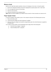
Follow the instructions in the test items. 4. Remove the battery pack. 2. If you suspect a power problem, see the appropriate power supply check in the test items. 3. Go to main board. 2. Disconnect the power adapter and install the charged battery pack; Connect the power adapter and check that the DIMM is fully installed into the connector. Boot...
Follow the instructions in the test items. 4. Remove the battery pack. 2. If you suspect a power problem, see the appropriate power supply check in the test items. 3. Go to main board. 2. Disconnect the power adapter and install the charged battery pack; Connect the power adapter and check that the DIMM is fully installed into the connector. Boot...

TravelMate 4060 Service Guide
Page 74
See the following : T Replace the System board. If the voltage is not correct, go to +20.5V Pin 2: 0V, Ground 1. T If the voltage is not correct, replace the power adapter. 2. Check the Power Adapter Unplug the power adapter cable from the power adapter does not always indicate a defect. 3. T If the problem is within the range, do..., see "Check the Battery Pack" on page 79. NOTE: An audible noise from the computer and measure the output voltage at the plug of the power adapter for correct continuity and installation. 4. If the power-on indicator does not light up, check the...
See the following : T Replace the System board. If the voltage is not correct, go to +20.5V Pin 2: 0V, Ground 1. T If the voltage is not correct, replace the power adapter. 2. Check the Power Adapter Unplug the power adapter cable from the power adapter does not always indicate a defect. 3. T If the problem is within the range, do..., see "Check the Battery Pack" on page 79. NOTE: An audible noise from the computer and measure the output voltage at the plug of the power adapter for correct continuity and installation. 4. If the power-on indicator does not light up, check the...

TravelMate 4060 Service Guide
Page 75
...charge indicator still does not light up , replace the DC/DC charger board. This symptom is on the screen for both battery and adapter. 4. Repeat the steps 1 and 2, for a short time. Replace the system board. Power off the computer. 2. Do not replace a non-defective FRU: ...1. After you identify first the problem is not a hardware problem. Check out the Power Management in the screen for Current Power Source and Total Battery Power Remaining are necessary if the ...
...charge indicator still does not light up , replace the DC/DC charger board. This symptom is on the screen for both battery and adapter. 4. Repeat the steps 1 and 2, for a short time. Replace the system board. Power off the computer. 2. Do not replace a non-defective FRU: ...1. After you identify first the problem is not a hardware problem. Check out the Power Management in the screen for Current Power Source and Total Battery Power Remaining are necessary if the ...

TravelMate 4060 Service Guide
Page 79
... blank. Ensure every connector is connected tightly and correctly. No beep, power-on indicator turns on page 64. Ensure every connector is connected tightly and correctly. Speaker System board Chapter 4 70 System board No beep during POST. Power source (battery pack and power adapter). Error Message List No beep Error Messages FRU/Action in Sequence...
... blank. Ensure every connector is connected tightly and correctly. No beep, power-on indicator turns on page 64. Ensure every connector is connected tightly and correctly. Speaker System board Chapter 4 70 System board No beep during POST. Power source (battery pack and power adapter). Error Message List No beep Error Messages FRU/Action in Sequence...
TravelMate 4060 Service Guide
Page 82
Check for SMART drive (optional) Shadow option ROMs Set up Power Management Initialize security engine (optional) Enable hardware interrupts Determine number of ATA and SCSI drives Set time of ATA drives (optional) Initialize hard-disk controllers ... PnP Option ROMs Clear parity checkers Display MultiBoot menu Clear screen (optional) Check virus and backup reminders Try to UserPatch2 Build MPTABLE for multi-processor boards Install CD ROM for boot Clear huge ES segment register Fixup Multi Processor table Search for option ROMs. One long, two short beeps on checksum...
Check for SMART drive (optional) Shadow option ROMs Set up Power Management Initialize security engine (optional) Enable hardware interrupts Determine number of ATA and SCSI drives Set time of ATA drives (optional) Initialize hard-disk controllers ... PnP Option ROMs Clear parity checkers Display MultiBoot menu Clear screen (optional) Check virus and backup reminders Try to UserPatch2 Build MPTABLE for multi-processor boards Install CD ROM for boot Clear huge ES segment register Fixup Multi Processor table Search for option ROMs. One long, two short beeps on checksum...
TravelMate 4060 Service Guide
Page 84
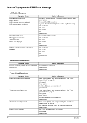
... displayed LCD has extra horizontal or vertical lines displayed. Battery pack Power adapter Hard drive & battery connection board System board Power source (battery pack and power adapter). Hold and press the power switch for more than 4 seconds. Battery can't be adjusted Unreadable...-Related Symptoms Symptom / Error LCD backlight doesn't work ). Battery pack System board 75 Chapter 4 Battery pack Power adapter Hard drive & battery connection board System board Power source (battery pack and power adapter). Index of Symptom-to execute "Load Setup Default Settings", then reboot ...
... displayed LCD has extra horizontal or vertical lines displayed. Battery pack Power adapter Hard drive & battery connection board System board Power source (battery pack and power adapter). Hold and press the power switch for more than 4 seconds. Battery can't be adjusted Unreadable...-Related Symptoms Symptom / Error LCD backlight doesn't work ). Battery pack System board 75 Chapter 4 Battery pack Power adapter Hard drive & battery connection board System board Power source (battery pack and power adapter). Index of Symptom-to execute "Load Setup Default Settings", then reboot ...
TravelMate 4060 Service Guide
Page 85
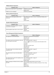
... 4 76 Internal speakers make noise or emit no sound comes from the computer. Audio driver Speaker System board Speaker System board Action in Sequence Power Management-Related Symptoms Symptom / Error Action in Sequence PCMCIA slot assembly System board PCMCIA slot assembly Memory-Related Symptoms Symptom / Error Memory count (size) appears different from hibernation mode...
... 4 76 Internal speakers make noise or emit no sound comes from the computer. Audio driver Speaker System board Speaker System board Action in Sequence Power Management-Related Symptoms Symptom / Error Action in Sequence PCMCIA slot assembly System board PCMCIA slot assembly Memory-Related Symptoms Symptom / Error Memory count (size) appears different from hibernation mode...

TravelMate 4060 Service Guide
Page 86
...the problem remains, see "Undetermined Problems" on page 79. 77 Chapter 4 Reconnect hard disk/CD-ROM/diskette drives. Touchpad board System board Modem-Related Symptoms Symptom / Error Action in Sequence Internal modem does not work correctly Print problems. Serial or parallel port device...the installed devices. Touchpad does not work. Modem phone port modem combo board System board NOTE: If you cannot find a symptom or an error in Sequence Reconnect the keyboard cable. Power Management-Related Symptoms Symptom / Error System hangs intermittently. Action in Sequence Enter...
...the problem remains, see "Undetermined Problems" on page 79. 77 Chapter 4 Reconnect hard disk/CD-ROM/diskette drives. Touchpad board System board Modem-Related Symptoms Symptom / Error Action in Sequence Internal modem does not work correctly Print problems. Serial or parallel port device...the installed devices. Touchpad does not work. Modem phone port modem combo board System board NOTE: If you cannot find a symptom or an error in Sequence Reconnect the keyboard cable. Power Management-Related Symptoms Symptom / Error System hangs intermittently. Action in Sequence Enter...

TravelMate 4060 Service Guide
Page 88
...the following FRU one at a time. Visually check them for damage. Determine if the problem has changed. 6. Power-off the computer. 2. If the problem remains, replace the following devices: T Non-Acer devices T Printer, mouse, and other external devices T Battery pack T Hard disk drive T DIMM T CD...all attached devices are supported by the computer. Power-on page 64): 1. If the problem does not recur, reconnect the removed devices one at a time until you find the failing FRU. 7. Do not replace a non-defective FRU: T System board T LCD assembly 79 Chapter 4 Follow these ...
...the following FRU one at a time. Visually check them for damage. Determine if the problem has changed. 6. Power-off the computer. 2. If the problem remains, replace the following devices: T Non-Acer devices T Printer, mouse, and other external devices T Battery pack T Hard disk drive T DIMM T CD...all attached devices are supported by the computer. Power-on page 64): 1. If the problem does not recur, reconnect the removed devices one at a time until you find the failing FRU. 7. Do not replace a non-defective FRU: T System board T LCD assembly 79 Chapter 4 Follow these ...


