Service Manual
Page 3
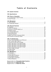
System Overview CH2. Theory of Operation 3.1 Fundamentals of Scanner 3300U 35 CH6. Specifications CH3. Electrical Systems 5.1 Overview...20 5.2 USB Port Interface...24 5.3 Scanner Controller (ASIC & µP 29 5.4 Analog Circuits ...31 5.5 CCD Head/Elements ...32 5.6 Line Motor Driver...33 5.7 Sensor Elements ...33 5.8 Main Flow Chart of Scanner 3300U 34 5.9 Connectors of Optic Process 6 3.2 Scan Process ...7 CH4. Troubleshooting 6.0 Error...
System Overview CH2. Theory of Operation 3.1 Fundamentals of Scanner 3300U 35 CH6. Specifications CH3. Electrical Systems 5.1 Overview...20 5.2 USB Port Interface...24 5.3 Scanner Controller (ASIC & µP 29 5.4 Analog Circuits ...31 5.5 CCD Head/Elements ...32 5.6 Line Motor Driver...33 5.7 Sensor Elements ...33 5.8 Main Flow Chart of Scanner 3300U 34 5.9 Connectors of Optic Process 6 3.2 Scan Process ...7 CH4. Troubleshooting 6.0 Error...
Service Manual
Page 4
..., and TWAIN 32 driver for PC. "Acer S2W 3300U" provides USB interface to communicate with ABET(Advanced Bit Enhanced Technology), capability of support 281 trillion colors, 16 bit grayscale, 1 bit line art Any TWAIN 32 compliant application can access this scanner. Chapter 1 System Overview "Acer S2W 3300U" is a popular flatbed color scanner with high speed, high quality, compact size...
..., and TWAIN 32 driver for PC. "Acer S2W 3300U" provides USB interface to communicate with ABET(Advanced Bit Enhanced Technology), capability of support 281 trillion colors, 16 bit grayscale, 1 bit line art Any TWAIN 32 compliant application can access this scanner. Chapter 1 System Overview "Acer S2W 3300U" is a popular flatbed color scanner with high speed, high quality, compact size...
Service Manual
Page 5
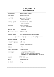
Chapter 2 Specifications Machine Type Scan Method Scan Mode Scanning Speed desktop flatbed scanner 1 pass, color CCD grayscale 16 bits/pixel color 48 bits/pixel monochrome 6.5 ms/line color 11.1ms/line Resolution Warm-up Time optical... resolution:1 dpi increment (optical resolution) to (maximum resolution): 2 dpi increment Highlight / shadow 256 steps Contrast / brightness 256 steps Interface Platforms Power Comsumption Power supply USB for host connection PC 25 W maximum Using 5 different AC adapters (100V,110V,120V,220V,240V) each can guarantee ±10% variation ;Frequency : 50 ~ ...
Chapter 2 Specifications Machine Type Scan Method Scan Mode Scanning Speed desktop flatbed scanner 1 pass, color CCD grayscale 16 bits/pixel color 48 bits/pixel monochrome 6.5 ms/line color 11.1ms/line Resolution Warm-up Time optical... resolution:1 dpi increment (optical resolution) to (maximum resolution): 2 dpi increment Highlight / shadow 256 steps Contrast / brightness 256 steps Interface Platforms Power Comsumption Power supply USB for host connection PC 25 W maximum Using 5 different AC adapters (100V,110V,120V,220V,240V) each can guarantee ±10% variation ;Frequency : 50 ~ ...

Service Manual
Page 7
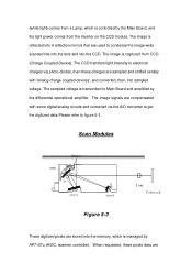
(4) Receiving The CCD receives the light, then transfers the intensity of the object (A4 or Letter), and show the object's size and position on the scanner's window glass and close the cover, then you want to scan on the monitor. (3) Pick Target In this stage, the user must decide the scanned ... voltage signals are data for better scanning image quality. (2) Preview The scan module scans roughly (75dpi) over all the range of light to close the scanner cover.
(4) Receiving The CCD receives the light, then transfers the intensity of the object (A4 or Letter), and show the object's size and position on the scanner's window glass and close the cover, then you want to scan on the monitor. (3) Pick Target In this stage, the user must decide the scanned ... voltage signals are data for better scanning image quality. (2) Preview The scan module scans roughly (75dpi) over all the range of light to close the scanner cover.
Service Manual
Page 10
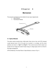
... Transmission Module Transmission Module 4.1 Optics Module The optics module includes lamp, reflect plate, three mirrors, lens, and CCD (charged couple device) board. Chapter 4 Mechanism The scanner's mechanism can exactly form an image and transform light energy to voltage signal, which is shown in Fig.4 -1 and Fig.4-2 .
... Transmission Module Transmission Module 4.1 Optics Module The optics module includes lamp, reflect plate, three mirrors, lens, and CCD (charged couple device) board. Chapter 4 Mechanism The scanner's mechanism can exactly form an image and transform light energy to voltage signal, which is shown in Fig.4 -1 and Fig.4-2 .
Service Manual
Page 14
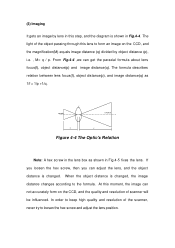
The light of the object passing through this lens to form an image on the CCD, and the quality and resolution of the scanner, never try to loosen the hex screw and adjust the lens position. If you loosen the hex screw, then you can not accurately form on ... lens focus(f), object distance(p) and image distance(q). When the object distance is changed , the image distance changes according to keep high quality and resolution of scanner will be influenced.
The light of the object passing through this lens to form an image on the CCD, and the quality and resolution of the scanner, never try to loosen the hex screw and adjust the lens position. If you loosen the hex screw, then you can not accurately form on ... lens focus(f), object distance(p) and image distance(q). When the object distance is changed , the image distance changes according to keep high quality and resolution of scanner will be influenced.

Service Manual
Page 15
... only to the intensity of the light. Note: The position of CCD and resulting in bad resolution for every scanner. It is fixed on a board, its position has been precisely calibrated for the scanner. Any deviation will output voltage signals while the light shines. It will seriously affect the output voltage of...
... only to the intensity of the light. Note: The position of CCD and resulting in bad resolution for every scanner. It is fixed on a board, its position has been precisely calibrated for the scanner. Any deviation will output voltage signals while the light shines. It will seriously affect the output voltage of...
Service Manual
Page 20
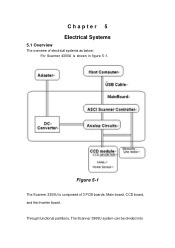
Figure 5-1 The Scanner 3300U is shown in figure 5-1. Through functional partitions, The Scanner 3300U system can be divided into Chapter 5 Electrical Systems 5.1 Overview The overview of electrical systems as below: For Scanner 4300U is composed of 3 PCB boards: Main board, CCD board, and the Inverter board.
Figure 5-1 The Scanner 3300U is shown in figure 5-1. Through functional partitions, The Scanner 3300U system can be divided into Chapter 5 Electrical Systems 5.1 Overview The overview of electrical systems as below: For Scanner 4300U is composed of 3 PCB boards: Main board, CCD board, and the Inverter board.
Service Manual
Page 21
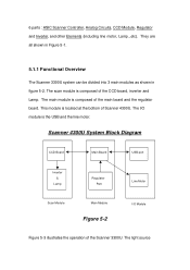
.... The light source They are all shown in Figure 5-1. 5.1.1 Functional Overview The Scanner 3300U system can be divided into 3 main modules as shown in figure 5-2. Scanner 4300U System Block Diagram CCD Board Main Board USB port Inverter & Lamp Regulator Part Line Motor Scan Module Main Module Figure 5-2 I /O module is composed of the CCD board...
.... The light source They are all shown in Figure 5-1. 5.1.1 Functional Overview The Scanner 3300U system can be divided into 3 main modules as shown in figure 5-2. Scanner 4300U System Block Diagram CCD Board Main Board USB port Inverter & Lamp Regulator Part Line Motor Scan Module Main Module Figure 5-2 I /O module is composed of the CCD board...
Service Manual
Page 22
... from the Inverter on the CCD module. The image is reflected into the CCD. (white light) comes from a Lamp, which is managed by AP7107u (ASIC, scanner controller).
... from the Inverter on the CCD module. The image is reflected into the CCD. (white light) comes from a Lamp, which is managed by AP7107u (ASIC, scanner controller).

Service Manual
Page 23
... CCD is used for the Cold Cathode Fluorescent Lamp. Block AC 110 Adapter +15V DC Voltage Regulator Converter Board Main Board Figure 5-4 3300U Scanner Main Board. Scanner 3300U Regulator board. A home sensor on the CCD board is co-operated with every scan-line. Block To get the whole image data,...AC voltage (~400 V) by a DC/AC inverter for the home positioning of the line-motor. transferred via SCSI bus, Printer port and USB cable to figure 5-4) transforms the adapter DC voltage into the required power sources. The switching regulator board (please refer to host computer.
... CCD is used for the Cold Cathode Fluorescent Lamp. Block AC 110 Adapter +15V DC Voltage Regulator Converter Board Main Board Figure 5-4 3300U Scanner Main Board. Scanner 3300U Regulator board. A home sensor on the CCD board is co-operated with every scan-line. Block To get the whole image data,...AC voltage (~400 V) by a DC/AC inverter for the home positioning of the line-motor. transferred via SCSI bus, Printer port and USB cable to figure 5-4) transforms the adapter DC voltage into the required power sources. The switching regulator board (please refer to host computer.
Service Manual
Page 24
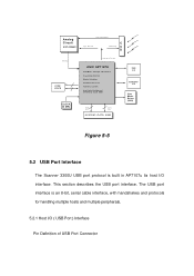
... for Motors) CPU(8032) &2.5K ROM Addr. Bus Data Bus SYSTEM / DATA RAM USB I/F ADF/TPO I/F Line Motor Driver (2003) Figure 5-5 5.2 USB Port Interface The Scanner 3300U USB port protocol is built in AP7107u its host I /O ( USB Port ) Interface Pin Definition of USB Port Connector Analog Circuit ASP A3568C ADC Bus CODE SRAM CLOCK 24 MHz CCD...
... for Motors) CPU(8032) &2.5K ROM Addr. Bus Data Bus SYSTEM / DATA RAM USB I/F ADF/TPO I/F Line Motor Driver (2003) Figure 5-5 5.2 USB Port Interface The Scanner 3300U USB port protocol is built in AP7107u its host I /O ( USB Port ) Interface Pin Definition of USB Port Connector Analog Circuit ASP A3568C ADC Bus CODE SRAM CLOCK 24 MHz CCD...

Service Manual
Page 29
... halftone processing for implement external CCD timing generator . 4.Built-in digital offset compensation. 5.Built-in digital shading to reduce number of an embedded CPU,USB controller M5611 and scanner controller. This ASIC also provides signals needed for binary image scanning. 10. Built-in CODE SRAM and does the following jobs: initialization, system...
... halftone processing for implement external CCD timing generator . 4.Built-in digital offset compensation. 5.Built-in digital shading to reduce number of an embedded CPU,USB controller M5611 and scanner controller. This ASIC also provides signals needed for binary image scanning. 10. Built-in CODE SRAM and does the following jobs: initialization, system...
Service Manual
Page 33
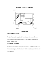
Given the clock pulses and the necessary power, it is very easy to interface with the bipolar stepping motor. 5.7 Sensor Elements The home sensor: a photo-interrupter is mounted on the CCD board to do the home positioning job, when the Scanner 4300U is drived by the 2003, a unipolar motor driver. Scanner 3300U CCD Board. 5.6 Line Motor Driver Figure 5-6 The Line Motor is calibrating or returning after finishing a scan.
Given the clock pulses and the necessary power, it is very easy to interface with the bipolar stepping motor. 5.7 Sensor Elements The home sensor: a photo-interrupter is mounted on the CCD board to do the home positioning job, when the Scanner 4300U is drived by the 2003, a unipolar motor driver. Scanner 3300U CCD Board. 5.6 Line Motor Driver Figure 5-6 The Line Motor is calibrating or returning after finishing a scan.
Service Manual
Page 34
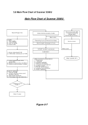
5.8 Main Flow Chart of Scanner 3300U Main Flow Chart of scan Next scan Adjust scanning parameters: 1.... "START SCAN" command Calibration Send scanned data (* control scanning timing and handshaking timing *) End of Scanner 3300U Start (Power On) Loader: 1. gamma correction 5. multi bit and single bit 6. scalling and resolution 9. System self... test : 1. window mode 7. Flash LED. 1. Check scanner motor and position sensor. 3. matrix operation Stop ( power off ) Check burn-in test Figure 5-7 Turn on lamp. ...
5.8 Main Flow Chart of Scanner 3300U Main Flow Chart of scan Next scan Adjust scanning parameters: 1.... "START SCAN" command Calibration Send scanned data (* control scanning timing and handshaking timing *) End of Scanner 3300U Start (Power On) Loader: 1. gamma correction 5. multi bit and single bit 6. scalling and resolution 9. System self... test : 1. window mode 7. Flash LED. 1. Check scanner motor and position sensor. 3. matrix operation Stop ( power off ) Check burn-in test Figure 5-7 Turn on lamp. ...
Service Manual
Page 35
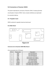
... 5.9.2 Main Board J8 J3 J2 U3 U4 Figure 5-9 U6 J5 U7 Connector J2 on Scanner 3300U Main Board J2 is connected to the CCD board. 5.9 Connectors of Scanner 3300U This section describes the connectors of Scanner 3300U, including all printed circuit boards in Scanner 3300U. Pin # 1 2 3 4 5 6 7 8 9 10 Signal name SHR SHG SHB PHI1 PHI2 PHIRS PHICP ~HSEN SHAD0...
... 5.9.2 Main Board J8 J3 J2 U3 U4 Figure 5-9 U6 J5 U7 Connector J2 on Scanner 3300U Main Board J2 is connected to the CCD board. 5.9 Connectors of Scanner 3300U This section describes the connectors of Scanner 3300U, including all printed circuit boards in Scanner 3300U. Pin # 1 2 3 4 5 6 7 8 9 10 Signal name SHR SHG SHB PHI1 PHI2 PHIRS PHICP ~HSEN SHAD0...

Service Manual
Page 36
... 1 of coil B Line motor pulse phase 1 of coil B- J1 FCC CONNECTOR J2 U5 CCD Figure 5-29 MOTOR POWER 5.9.3 CCD Board There are two connectors on Scanner 3300U Main Board J5 is connected to the line motor to drive the stepping motor. See figure 5-29. 11 PHISP 12 OS 13 DG 14 NC... +15V Digital power +5V No Connection Digital power ground Digital power ground No Connection Lamp +12V Lamp +12V Connector J5 on the CCD board in 3300U Scanner. Pin # 1 2 3 4 5 Signal name A AB B-
... 1 of coil B Line motor pulse phase 1 of coil B- J1 FCC CONNECTOR J2 U5 CCD Figure 5-29 MOTOR POWER 5.9.3 CCD Board There are two connectors on Scanner 3300U Main Board J5 is connected to the line motor to drive the stepping motor. See figure 5-29. 11 PHISP 12 OS 13 DG 14 NC... +15V Digital power +5V No Connection Digital power ground Digital power ground No Connection Lamp +12V Lamp +12V Connector J5 on the CCD board in 3300U Scanner. Pin # 1 2 3 4 5 Signal name A AB B-
Service Manual
Page 37
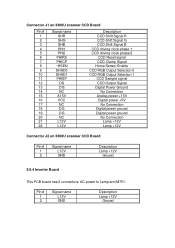
Connector J1 on 3300U scanner CCD Board Pin # 1 2 3 4 5 6 7 8 9 10 11 12 13 14 15 16 17 18 19 20 21 22 Signal name SHR SHG SHB PHI1 PHI2 PHIRS PHICP ~... No Connection Analog power +15V Digital power +5V No Connection Digital power ground Digital power ground No Connection Lamp +12V Lamp +12V Connector J2 on 3300U scanner CCD Board Pin # 1 2 Signal name L12V GND Description Lamp +12V Ground 5.9.4 Inverter Board This PCB board has 2 connectors: AC power to Lamp and M751. Pin...
Connector J1 on 3300U scanner CCD Board Pin # 1 2 3 4 5 6 7 8 9 10 11 12 13 14 15 16 17 18 19 20 21 22 Signal name SHR SHG SHB PHI1 PHI2 PHIRS PHICP ~... No Connection Analog power +15V Digital power +5V No Connection Digital power ground Digital power ground No Connection Lamp +12V Lamp +12V Connector J2 on 3300U scanner CCD Board Pin # 1 2 Signal name L12V GND Description Lamp +12V Ground 5.9.4 Inverter Board This PCB board has 2 connectors: AC power to Lamp and M751. Pin...
Service Manual
Page 41
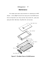
Chapter 7 Maintenance This chapter gives step by step instructions for maintaining the 640BT Scanner. And the Fig.7-1 shows the five major parts of SLIM6 Scanner Figure7-1 The Main Parts of the SLIM6 Scanner, there are Assy Book cover, Assy Up-Case, Assy module Set , pulley seat, spring, belt, Shaft , Main Board , Assy Motor-Set , and Low-case.
Chapter 7 Maintenance This chapter gives step by step instructions for maintaining the 640BT Scanner. And the Fig.7-1 shows the five major parts of SLIM6 Scanner Figure7-1 The Main Parts of the SLIM6 Scanner, there are Assy Book cover, Assy Up-Case, Assy module Set , pulley seat, spring, belt, Shaft , Main Board , Assy Motor-Set , and Low-case.
Service Manual
Page 42
...connector by reversing the disassembly procedure. - Never turn the power on if there is shown in the direction that you unplug the SLIM6 Scanner before disassembling. - Do not disassemble the CCD board and lens. - Lift up the cover and cover hinge in Fig.7-2. Unless otherwise ...specified, reassemble the scanner by holding the connector housing. Keep your hands and clothing well away from the operating or moving parts such as scan module, gear train...
...connector by reversing the disassembly procedure. - Never turn the power on if there is shown in the direction that you unplug the SLIM6 Scanner before disassembling. - Do not disassemble the CCD board and lens. - Lift up the cover and cover hinge in Fig.7-2. Unless otherwise ...specified, reassemble the scanner by holding the connector housing. Keep your hands and clothing well away from the operating or moving parts such as scan module, gear train...

