Service Manual
Page 3
... show 0XFFFF0026 39 6.6 When MicraScan show 0XFFFF0027 39 6.7 Scan Quality not Good 39 6.8 Power Supply...39 6.9 CCD Head ...40 CH7. System Overview CH2. Electrical Systems 5.1 Overview...20 5.2 USB Port Interface...24 5.3 Scanner Controller (ASIC & µP 29 5.4 Analog Circuits ...31 5.5 CCD Head/Elements ...32 5.6 Line Motor Driver...33 5.7 Sensor Elements ...33 5.8 Main Flow Chart of Scanner 3300U 34 5.9 Connectors of Scanner 3300U 35 CH6.
... show 0XFFFF0026 39 6.6 When MicraScan show 0XFFFF0027 39 6.7 Scan Quality not Good 39 6.8 Power Supply...39 6.9 CCD Head ...40 CH7. System Overview CH2. Electrical Systems 5.1 Overview...20 5.2 USB Port Interface...24 5.3 Scanner Controller (ASIC & µP 29 5.4 Analog Circuits ...31 5.5 CCD Head/Elements ...32 5.6 Line Motor Driver...33 5.7 Sensor Elements ...33 5.8 Main Flow Chart of Scanner 3300U 34 5.9 Connectors of Scanner 3300U 35 CH6.
Service Manual
Page 4
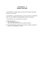
... trillion colors, 16 bit grayscale, 1 bit line art "Acer S2W 3300U" other main features are as following: n High quality resolution 600 x 1200 dpi optical resolution 19200 x 19200 dpi maximum resolution by software interpolation n 48 bit with high speed, high quality, compact size, and low price. Any TWAIN 32 compliant application can access this scanner. "Acer S2W 3300U" provides USB interface to communicate with host, and TWAIN 32 driver...
... trillion colors, 16 bit grayscale, 1 bit line art "Acer S2W 3300U" other main features are as following: n High quality resolution 600 x 1200 dpi optical resolution 19200 x 19200 dpi maximum resolution by software interpolation n 48 bit with high speed, high quality, compact size, and low price. Any TWAIN 32 compliant application can access this scanner. "Acer S2W 3300U" provides USB interface to communicate with host, and TWAIN 32 driver...
Service Manual
Page 5
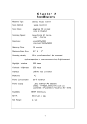
... bits/pixel color 48 bits/pixel monochrome 6.5 ms/line color 11.1ms/line Resolution Warm-up Time optical 600x1200 maximum 19200x19200 15 seconds Maximum Scan Area 8.5" X 11.7" Scanning density 12 to optical resolution:1 dpi increment (optical resolution) to (maximum resolution): 2 dpi increment Highlight / shadow 256 steps Contrast / brightness 256 steps Interface Platforms Power Comsumption Power supply USB for host connection PC 25 W maximum Using...
... bits/pixel color 48 bits/pixel monochrome 6.5 ms/line color 11.1ms/line Resolution Warm-up Time optical 600x1200 maximum 19200x19200 15 seconds Maximum Scan Area 8.5" X 11.7" Scanning density 12 to optical resolution:1 dpi increment (optical resolution) to (maximum resolution): 2 dpi increment Highlight / shadow 256 steps Contrast / brightness 256 steps Interface Platforms Power Comsumption Power supply USB for host connection PC 25 W maximum Using...
Service Manual
Page 6
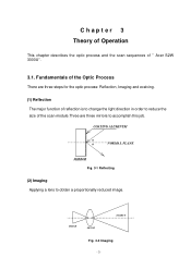
COATING ALUMINUM a a NORMAL PLANE MIRROR Fig. 3-1 Reflecting (2) Imaging Applying a lens to accomplish this job. Fundamentals of the Optic Process There are three steps for the optic process: Reflection, Imaging and eceiving. (1) Reflection The major function of reflection is to change the light direction in order to reduce the size of " Acer S2W 3300U". 3.1. Chapter 3 Theory of Operation This chapter describes the optic process and the scan sequences of the scan module.Three are three mirrors to obtain a proportionally reduced image. IMAGE LENSE OBJECT Fig. 3-2 Imaging
COATING ALUMINUM a a NORMAL PLANE MIRROR Fig. 3-1 Reflecting (2) Imaging Applying a lens to accomplish this job. Fundamentals of the Optic Process There are three steps for the optic process: Reflection, Imaging and eceiving. (1) Reflection The major function of reflection is to change the light direction in order to reduce the size of " Acer S2W 3300U". 3.1. Chapter 3 Theory of Operation This chapter describes the optic process and the scan sequences of the scan module.Three are three mirrors to obtain a proportionally reduced image. IMAGE LENSE OBJECT Fig. 3-2 Imaging

Service Manual
Page 7
... The scan module scans roughly (75dpi) over all the range of light to scan on the monitor. (3) Pick Target In this stage, the user must decide the scanned area and position. (4) Receiving The CCD receives the light, then transfers the intensity of the object (A4 or Letter), and show the object's size and position on the scanner's window glass and close the scanner cover.
... The scan module scans roughly (75dpi) over all the range of light to scan on the monitor. (3) Pick Target In this stage, the user must decide the scanned area and position. (4) Receiving The CCD receives the light, then transfers the intensity of the object (A4 or Letter), and show the object's size and position on the scanner's window glass and close the scanner cover.
Service Manual
Page 21
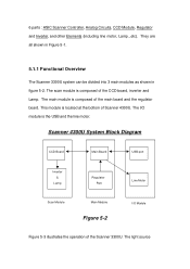
... the operation of Scanner 4300U. The light source The scan module is the USB and the line motor. Scanner 4300U System Block Diagram CCD Board Main Board USB port Inverter & Lamp Regulator Part Line Motor Scan Module Main Module Figure 5-2 I /O module is composed of the main board and the regulator board. The main module is located at the bottom of the Scanner 3300U. 6 parts : ASIC Scanner Controller, Analog...
... the operation of Scanner 4300U. The light source The scan module is the USB and the line motor. Scanner 4300U System Block Diagram CCD Board Main Board USB port Inverter & Lamp Regulator Part Line Motor Scan Module Main Module Figure 5-2 I /O module is composed of the main board and the regulator board. The main module is located at the bottom of the Scanner 3300U. 6 parts : ASIC Scanner Controller, Analog...
Service Manual
Page 22
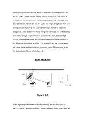
... Device). The image is reflected into 6 reflection mirrors that are used to condense the image-wide scanned line into the lens and into sampled voltage. The CCD transfers light intensity to electrical charges via the A/D converter to get the digitized data.Please refer to figure 5-3. When requested, these charges are The sampled voltage is managed by AP7107u (ASIC, scanner controller). Scan Modules Object lamp 2 4 6 1 5 3 Lens Color...
... Device). The image is reflected into 6 reflection mirrors that are used to condense the image-wide scanned line into the lens and into sampled voltage. The CCD transfers light intensity to electrical charges via the A/D converter to get the digitized data.Please refer to figure 5-3. When requested, these charges are The sampled voltage is managed by AP7107u (ASIC, scanner controller). Scan Modules Object lamp 2 4 6 1 5 3 Lens Color...

Service Manual
Page 23
... 5-4 3300U Scanner Main Board. If a color image is requested, the color CCD is used for the Cold Cathode Fluorescent Lamp. A home sensor on the CCD board is co-operated with every scan-line. An inverter board converts DC 12V to host computer. To get the whole image data, the line motor steps forward to figure 5-4) transforms the adapter DC voltage into the required power sources. transferred via SCSI...
... 5-4 3300U Scanner Main Board. If a color image is requested, the color CCD is used for the Cold Cathode Fluorescent Lamp. A home sensor on the CCD board is co-operated with every scan-line. An inverter board converts DC 12V to host computer. To get the whole image data, the line motor steps forward to figure 5-4) transforms the adapter DC voltage into the required power sources. transferred via SCSI...
Service Manual
Page 24
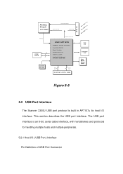
... interface. Analog Circuit ASP A3568C ADC Bus CODE SRAM CLOCK 24 MHz CCD Video Output Sync. The USB port interface is an 8-bit, serial cable interface, with handshakes and protocols for Motors) CPU(8032) &2.5K ROM Addr. Bus Data Bus SYSTEM / DATA RAM USB I/F ADF/TPO I/F Line Motor Driver (2003) Figure 5-5 5.2 USB Port Interface The Scanner 3300U USB port protocol is built in AP7107u its...
... interface. Analog Circuit ASP A3568C ADC Bus CODE SRAM CLOCK 24 MHz CCD Video Output Sync. The USB port interface is an 8-bit, serial cable interface, with handshakes and protocols for Motors) CPU(8032) &2.5K ROM Addr. Bus Data Bus SYSTEM / DATA RAM USB I/F ADF/TPO I/F Line Motor Driver (2003) Figure 5-5 5.2 USB Port Interface The Scanner 3300U USB port protocol is built in AP7107u its...

Service Manual
Page 29
...-level/color scanning. 9. Provide 6 output pins to control line motor. 10. Built-in CODE SRAM and does the following jobs: initialization, system selftest, calibration, panel handling, scan handling USB port interface and other signal control. 5.3.1 Features The AP7107u (ASIC) includes the following features: 1. 12 bit CCD data input. Built-in scanner circuits. 7. Scanner Controller (ASIC & µ P) The scanner controller consists of analog parts in halftone processing for binary scanning. 2.Support monochrome...
...-level/color scanning. 9. Provide 6 output pins to control line motor. 10. Built-in CODE SRAM and does the following jobs: initialization, system selftest, calibration, panel handling, scan handling USB port interface and other signal control. 5.3.1 Features The AP7107u (ASIC) includes the following features: 1. 12 bit CCD data input. Built-in scanner circuits. 7. Scanner Controller (ASIC & µ P) The scanner controller consists of analog parts in halftone processing for binary scanning. 2.Support monochrome...
Service Manual
Page 34
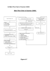
... Initial communication mode Next scan Receving host command and data Send target message to host "START SCAN" command Calibration Send scanned data (* control scanning timing and handshaking timing *) End of F/W 1. scalling and resolution 9. Yes Burn-in No mode ? Check scanner motor and position sensor. 3. contrast 3. Reset communication mode. Reset components condition. 3. Turn on lamp. 4. Driver download F/W 2. brightness 2. matrix operation Stop ( power off ) Check burn-in test Figure 5-7 H/W verify chechsum of scan Next scan Adjust scanning parameters: 1. System...
... Initial communication mode Next scan Receving host command and data Send target message to host "START SCAN" command Calibration Send scanned data (* control scanning timing and handshaking timing *) End of F/W 1. scalling and resolution 9. Yes Burn-in No mode ? Check scanner motor and position sensor. 3. contrast 3. Reset communication mode. Reset components condition. 3. Turn on lamp. 4. Driver download F/W 2. brightness 2. matrix operation Stop ( power off ) Check burn-in test Figure 5-7 H/W verify chechsum of scan Next scan Adjust scanning parameters: 1. System...
Service Manual
Page 38
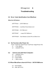
... LED flashes : 0XFFFF0021 --- DATA SRAM U7 --- Lamp/CCD GAIN error 0XFFFF002A --- ASIC(AP7107u) U4 --- DC Offset error 0XFFFF0027 --- USB connector 6.3 When MicraScan show 0XFFFF0021 : DATA RAM error U4 --- XTAL 24MHZ U3 --- ASIC(AP7107U) 6.2 Cannot Link with Host Computer: U3 --- DATA SRAM U3 --- Scan Module Locked OR Line Motor Error 6.1 No Function after Power On: Power Cord/Power Switch/Power Fuse/Power Supply/Power Part X1 --- CODE SRAM J8 --- ASIC (AP7107U) DATA RAM error 0XFFFF0024 --- Line Motor/Home Sensor error...
... LED flashes : 0XFFFF0021 --- DATA SRAM U7 --- Lamp/CCD GAIN error 0XFFFF002A --- ASIC(AP7107u) U4 --- DC Offset error 0XFFFF0027 --- USB connector 6.3 When MicraScan show 0XFFFF0021 : DATA RAM error U4 --- XTAL 24MHZ U3 --- ASIC(AP7107U) 6.2 Cannot Link with Host Computer: U3 --- DATA SRAM U3 --- Scan Module Locked OR Line Motor Error 6.1 No Function after Power On: Power Cord/Power Switch/Power Fuse/Power Supply/Power Part X1 --- CODE SRAM J8 --- ASIC (AP7107U) DATA RAM error 0XFFFF0024 --- Line Motor/Home Sensor error...
Service Manual
Page 42
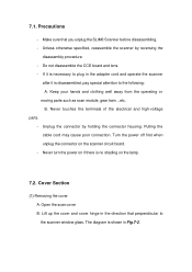
... scanner window glass. Turn the power off first when unplug the connector on the lamp. 7.2. Unplug the connector by reversing the disassembly procedure. - Pulling the cable cord may cause poor connection. Open the scan cover B. If it is shown in the direction that you unplug the SLIM6 Scanner before disassembling. - Cover Section (1) Removing the cover A. The diagram is disassembled, pay special attention to plug in the adapter cord and operate...
... scanner window glass. Turn the power off first when unplug the connector on the lamp. 7.2. Unplug the connector by reversing the disassembly procedure. - Pulling the cable cord may cause poor connection. Open the scan cover B. If it is shown in the direction that you unplug the SLIM6 Scanner before disassembling. - Cover Section (1) Removing the cover A. The diagram is disassembled, pay special attention to plug in the adapter cord and operate...
Service Manual
Page 53
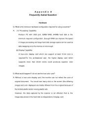
... use the true color card? However, the data captured by the scanner is required.For the professional user, the higher display card which can improve the speed of display card. Enough RAM can support at least 16-bit color is not affected; Q: What would see many dots on the screen (the dithering image) and color displayed are totally different from the original because of original document...
... use the true color card? However, the data captured by the scanner is required.For the professional user, the higher display card which can improve the speed of display card. Enough RAM can support at least 16-bit color is not affected; Q: What would see many dots on the screen (the dithering image) and color displayed are totally different from the original because of original document...
Service Manual
Page 54
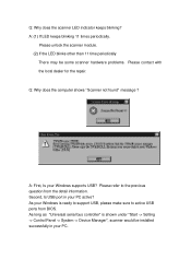
... support USB, please make sure to the previous question from BIOS. Please unlock the scanner module. (2) If the LED blinks other than 11 time periodically There may be installed successfully in your Windows supports USB? Second, Is USB port in your Windows is shown under "Start -> Setting -> Control Panel -> System -> Device Manager", scanner would be some scanner hardware problems. Please contact with the local dealer for the repair. A: (1) If LED keeps blinking...
... support USB, please make sure to the previous question from BIOS. Please unlock the scanner module. (2) If the LED blinks other than 11 time periodically There may be installed successfully in your Windows supports USB? Second, Is USB port in your Windows is shown under "Start -> Setting -> Control Panel -> System -> Device Manager", scanner would be some scanner hardware problems. Please contact with the local dealer for the repair. A: (1) If LED keeps blinking...
Service Manual
Page 55
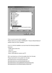
... most update driver from the web, Please download the most update from the web: http://www.acercm.com.au/service/index.htm http://www.acercm-eu.com/downloads/index.cfm http://www.acercm.com.tw/global/service/scan/drivers.htm http://www.acercm.com/drivers/imaging_drivers.html install scanner driver first - plug in "Scanner Model Selection" window during the driver installation. Third, Is correct scanner driver installed? reboot PC - power on scanner - Fourth...
... most update driver from the web, Please download the most update from the web: http://www.acercm.com.au/service/index.htm http://www.acercm-eu.com/downloads/index.cfm http://www.acercm.com.tw/global/service/scan/drivers.htm http://www.acercm.com/drivers/imaging_drivers.html install scanner driver first - plug in "Scanner Model Selection" window during the driver installation. Third, Is correct scanner driver installed? reboot PC - power on scanner - Fourth...
Service Manual
Page 56
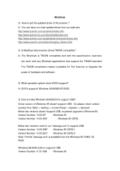
....5 Note: The file "usbsupp.exe" is TWAIN compatible and with this specification, scanners can have our most updated driver from "Start -> Setting -> Control Panel -> System -> General". Windows 98 The TWAIN compliance makes it possible for The Scanner to integrate the power of the scanner ? Below two versions doesn't support USB, so please upgrade to support USB. Windows 95 OSR2.1 Version Number: "4.00.95C" - A: The MiraScan is available from the Windows 95 OSR2 CD ROM. A: 3300U supports Windows 95/98...
....5 Note: The file "usbsupp.exe" is TWAIN compatible and with this specification, scanners can have our most updated driver from "Start -> Setting -> Control Panel -> System -> General". Windows 98 The TWAIN compliance makes it possible for The Scanner to integrate the power of the scanner ? Below two versions doesn't support USB, so please upgrade to support USB. Windows 95 OSR2.1 Version Number: "4.00.95C" - A: The MiraScan is available from the Windows 95 OSR2 CD ROM. A: 3300U supports Windows 95/98...

Service Manual
Page 57
... do any good to use the most update MiraScan driver. Windows NT doesn't support USB. Q: What if there are unwanted color lines on the output printing device. (1) Continuous tone color printer (such as dye-sublimation printer) The scanning resolution should be set the same as the resolution of the printer. Please contact the local dealer or supplier for the repair. A: (1) Please make sure that the scanning windows is always blurry...
... do any good to use the most update MiraScan driver. Windows NT doesn't support USB. Q: What if there are unwanted color lines on the output printing device. (1) Continuous tone color printer (such as dye-sublimation printer) The scanning resolution should be set the same as the resolution of the printer. Please contact the local dealer or supplier for the repair. A: (1) Please make sure that the scanning windows is always blurry...

Service Manual
Page 58
... MiraScan driver? We recommend that you can upgrade you system to Hi-color mode, so that all the colors can be able to see all the color data. Photo Express Q. Not all image software support 48-bit scanning image? A: If your original picture has although the scanner has gotten all the colors that your monitor(output device) only provide 256 colors or less, you disregard the Hi-color warning message...
... MiraScan driver? We recommend that you can upgrade you system to Hi-color mode, so that all the colors can be able to see all the color data. Photo Express Q. Not all image software support 48-bit scanning image? A: If your original picture has although the scanner has gotten all the colors that your monitor(output device) only provide 256 colors or less, you disregard the Hi-color warning message...

Service Manual
Page 59
....S0801.001 34.S0805.001 N/A 55.S0803.001 Warranty Card Guide quick soap CD Soap III Blank carton label Book cover Hinge (must 2*) Spec Label. (Blank) Name Plate V. A p p e n d i x B : Spare Parts List Acer S2W 3300U (99.S0861.X3X) 6678-O3E(N/B) Based on Exchange Rate...Scan to palm) $0.26 CD $0.99 CD Manual 17L $0.50 Warranty CARD Dan-Chin Tradi. PCBA Generic 47.S0809.001 47.S0810.001 42.69511.001 42.03809.011 46.S0809.002 V4.06 N/A CCD Moudle M/B M/B Cover Panel (Button) Board Inverter/B IV. Packing Material Carton $1.56 Cushion Left $0.20 Cushion Right $0.20 Scanner...
....S0801.001 34.S0805.001 N/A 55.S0803.001 Warranty Card Guide quick soap CD Soap III Blank carton label Book cover Hinge (must 2*) Spec Label. (Blank) Name Plate V. A p p e n d i x B : Spare Parts List Acer S2W 3300U (99.S0861.X3X) 6678-O3E(N/B) Based on Exchange Rate...Scan to palm) $0.26 CD $0.99 CD Manual 17L $0.50 Warranty CARD Dan-Chin Tradi. PCBA Generic 47.S0809.001 47.S0810.001 42.69511.001 42.03809.011 46.S0809.002 V4.06 N/A CCD Moudle M/B M/B Cover Panel (Button) Board Inverter/B IV. Packing Material Carton $1.56 Cushion Left $0.20 Cushion Right $0.20 Scanner...


