Service Manual
Page 3
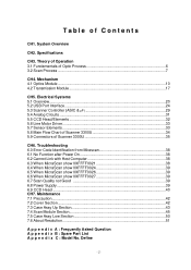
.... Table of Optic Process 6 3.2 Scan Process ...7 CH4. Electrical Systems 5.1 Overview...20 5.2 USB Port Interface...24 5.3 Scanner Controller (ASIC & µP 29 5.4 Analog Circuits ...31 5.5 CCD Head/Elements ...32 5.6 Line Motor Driver...33 5.7 Sensor Elements ...33 5.8 Main Flow Chart of Scanner 3300U 34 5.9 Connectors of Scanner 3300U 35 CH6. Troubleshooting 6.0 Error Code Identification from Mirascan 38 6.1 No Function after...
.... Table of Optic Process 6 3.2 Scan Process ...7 CH4. Electrical Systems 5.1 Overview...20 5.2 USB Port Interface...24 5.3 Scanner Controller (ASIC & µP 29 5.4 Analog Circuits ...31 5.5 CCD Head/Elements ...32 5.6 Line Motor Driver...33 5.7 Sensor Elements ...33 5.8 Main Flow Chart of Scanner 3300U 34 5.9 Connectors of Scanner 3300U 35 CH6. Troubleshooting 6.0 Error Code Identification from Mirascan 38 6.1 No Function after...
Service Manual
Page 4
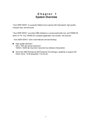
Chapter 1 System Overview "Acer S2W 3300U" is a popular flatbed color scanner with host, and TWAIN 32 driver for PC. Any TWAIN 32 compliant application can access this scanner. "Acer S2W 3300U" provides USB interface to communicate with high speed, high quality, compact size, and low price. "Acer S2W 3300U" other main features are as following: n High quality resolution 600 x 1200 dpi optical resolution 19200...
Chapter 1 System Overview "Acer S2W 3300U" is a popular flatbed color scanner with host, and TWAIN 32 driver for PC. Any TWAIN 32 compliant application can access this scanner. "Acer S2W 3300U" provides USB interface to communicate with high speed, high quality, compact size, and low price. "Acer S2W 3300U" other main features are as following: n High quality resolution 600 x 1200 dpi optical resolution 19200...
Service Manual
Page 24
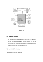
.... 5.2.1 Host I /O interface. This section describes the USB port interface. The USB port interface is an 8-bit, serial cable interface, with handshakes and protocols for Motors) CPU(8032) &2.5K ROM Addr. Bus Data Bus SYSTEM / DATA RAM USB I/F ADF/TPO I/F Line Motor Driver (2003) Figure 5-5 5.2 USB Port Interface The Scanner 3300U USB port protocol is built in AP7107u its...
.... 5.2.1 Host I /O interface. This section describes the USB port interface. The USB port interface is an 8-bit, serial cable interface, with handshakes and protocols for Motors) CPU(8032) &2.5K ROM Addr. Bus Data Bus SYSTEM / DATA RAM USB I/F ADF/TPO I/F Line Motor Driver (2003) Figure 5-5 5.2 USB Port Interface The Scanner 3300U USB port protocol is built in AP7107u its...
Service Manual
Page 25
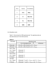
... below and in the follow sections. Data line 3 D+ Data line 4 GND GND 5.2.2 Signaling Levels Table 5-1 Summarizes the USB signaling levels. Pin # Source Pin Definition 1 VCC VBus 2 D- Table 5-1 BUS State Differential "1" Differential "0" Data J State...: Low Speed Full Speed Data K State: Low Speed Full Speed Idle State: Low Speed Fill Speed Signaling Levels Form Originating Driver At Receiver (D+)-(D-) > 200 mV and D+ or D- > VSE(min) (D+)-(D-) < 200 mV and D+ or D- > VSE(min) Differential "0" Differential "1" Differential...
... below and in the follow sections. Data line 3 D+ Data line 4 GND GND 5.2.2 Signaling Levels Table 5-1 Summarizes the USB signaling levels. Pin # Source Pin Definition 1 VCC VBus 2 D- Table 5-1 BUS State Differential "1" Differential "0" Data J State...: Low Speed Full Speed Data K State: Low Speed Full Speed Idle State: Low Speed Fill Speed Signaling Levels Form Originating Driver At Receiver (D+)-(D-) > 200 mV and D+ or D- > VSE(min) (D+)-(D-) < 200 mV and D+ or D- > VSE(min) Differential "0" Differential "1" Differential...

Service Manual
Page 27
... to less than D- 5.2.3 Data Signaling Data transmission within a packet is represented by D+ being at the receiver, and a differential 0 is indicated by both the D+ and Doutput drivers are placed in the idle state. The single-ended 0 state is represented by driving d+ and D- The single-ended 0 state is asserted for 1 bit time and...
... to less than D- 5.2.3 Data Signaling Data transmission within a packet is represented by D+ being at the receiver, and a differential 0 is indicated by both the D+ and Doutput drivers are placed in the idle state. The single-ended 0 state is represented by driving d+ and D- The single-ended 0 state is asserted for 1 bit time and...
Service Manual
Page 33
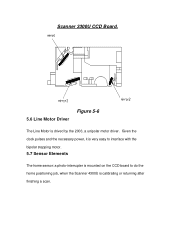
Given the clock pulses and the necessary power, it is very easy to interface with the bipolar stepping motor. 5.7 Sensor Elements The home sensor: a photo-interrupter is mounted on the CCD board to do the home positioning job, when the Scanner 4300U is drived by the 2003, a unipolar motor driver. Scanner 3300U CCD Board. 5.6 Line Motor Driver Figure 5-6 The Line Motor is calibrating or returning after finishing a scan.
Given the clock pulses and the necessary power, it is very easy to interface with the bipolar stepping motor. 5.7 Sensor Elements The home sensor: a photo-interrupter is mounted on the CCD board to do the home positioning job, when the Scanner 4300U is drived by the 2003, a unipolar motor driver. Scanner 3300U CCD Board. 5.6 Line Motor Driver Figure 5-6 The Line Motor is calibrating or returning after finishing a scan.
Service Manual
Page 34
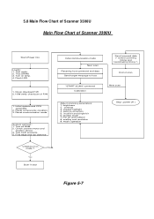
Test SRAM. 3. contrast 3. multi bit and single bit 6. Driver download F/W 2. Test CCD and lamp 5. scalling and resolution 9. Test motor. 2. Test all RAM. 2. brightness 2. line art and halftone 8. shadow-highlight 4. Flash ... target message to host "START SCAN" command Calibration Send scanned data (* control scanning timing and handshaking timing *) End of Scanner 3300U Start (Power On) Loader: 1. 5.8 Main Flow Chart of Scanner 3300U Main Flow Chart of scan Next scan Adjust scanning parameters: 1. matrix operation Stop ( power off ) Check burn-in test...
Test SRAM. 3. contrast 3. multi bit and single bit 6. Driver download F/W 2. Test CCD and lamp 5. scalling and resolution 9. Test motor. 2. Test all RAM. 2. brightness 2. line art and halftone 8. shadow-highlight 4. Flash ... target message to host "START SCAN" command Calibration Send scanned data (* control scanning timing and handshaking timing *) End of Scanner 3300U Start (Power On) Loader: 1. 5.8 Main Flow Chart of Scanner 3300U Main Flow Chart of scan Next scan Adjust scanning parameters: 1. matrix operation Stop ( power off ) Check burn-in test...
Service Manual
Page 55
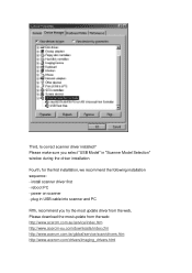
Third, Is correct scanner driver installed? install scanner driver first - power on scanner - reboot PC - plug in USB cable into scanner and PC Fifth, recommend you select "USB Model" in "Scanner Model Selection" window during the driver installation. Fourth, for the first installation, we recommend the following installation sequence: - Please make sure you try the most update driver from the web, Please...
Third, Is correct scanner driver installed? install scanner driver first - power on scanner - reboot PC - plug in USB cable into scanner and PC Fifth, recommend you select "USB Model" in "Scanner Model Selection" window during the driver installation. Fourth, for the first installation, we recommend the following installation sequence: - Please make sure you try the most update driver from the web, Please...
Service Manual
Page 56
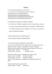
....cfm http://www.acercm.com.tw/global/service/scan/drivers.htm http://www.acercm.com/drivers/imaging_drivers.html Q: Is MiraScan (the scanner driver) TWAIN compatible? A: The MiraScan is available from the Windows 95 OSR2 CD ROM. Q: What operation system does 3300U support? MiraScan Q : How to support USB. Q: How to make Windows 95/98/2000 to support...
....cfm http://www.acercm.com.tw/global/service/scan/drivers.htm http://www.acercm.com/drivers/imaging_drivers.html Q: Is MiraScan (the scanner driver) TWAIN compatible? A: The MiraScan is available from the Windows 95 OSR2 CD ROM. Q: What operation system does 3300U support? MiraScan Q : How to support USB. Q: How to make Windows 95/98/2000 to support...

Service Manual
Page 57
...that the scanning windows is the proper resolution setting? Q: What is clean. (2) Try to use the most update MiraScan driver. The web site is depends on the output printing device. (1) Continuous tone color printer (such as dye-sublimation printer)...index.htm http://www.acercm-eu.com/downloads/index.cfm http://www.acercm.com.tw/global/service/scan/drivers.htm http://www.acercm.com/drivers/imaging_drivers.html (3) If the above two options can't solve the problem, the scan module may ...be damaged during the shipping. The general idea is always blurry? Windows NT doesn't support USB.
...that the scanning windows is the proper resolution setting? Q: What is clean. (2) Try to use the most update MiraScan driver. The web site is depends on the output printing device. (1) Continuous tone color printer (such as dye-sublimation printer)...index.htm http://www.acercm-eu.com/downloads/index.cfm http://www.acercm.com.tw/global/service/scan/drivers.htm http://www.acercm.com/drivers/imaging_drivers.html (3) If the above two options can't solve the problem, the scan module may ...be damaged during the shipping. The general idea is always blurry? Windows NT doesn't support USB.

Service Manual
Page 58
... MiraScan Q: Does all image software support 48-bit format image. If the user do scanning with 48-bit in software which comes with the scanner) and Photo Shop 5.0 support 48-bit image. Currently, Ulead Photo Express 3.0 (which do I get the Hi-Color warning every time I'm acquiring ...the MiraScan driver? Photo Express Q. Why do not support, then the software system might be displayed on your monitor. Not all image software support 48-bit scanning ...
... MiraScan Q: Does all image software support 48-bit format image. If the user do scanning with 48-bit in software which comes with the scanner) and Photo Shop 5.0 support 48-bit image. Currently, Ulead Photo Express 3.0 (which do I get the Hi-Color warning every time I'm acquiring ...the MiraScan driver? Photo Express Q. Why do not support, then the software system might be displayed on your monitor. Not all image software support 48-bit scanning ...


