
Power FV and Aspire T600 Service Guide
Page 6
...1 Overview 1 Features 2 Aspire T600 Front Panel 4 Aspire T600 Rear Panel 5 Acer Power FV Front Panel 6 AcerPower FV Rear Panel 7 System Peripherals 8 MainBoard Layout 10 Block Diagram 11 Hardware Specifications and Configurations 12 Power Management Function (ACPI support function 20 Chapter 2 System Utilities 21 Entering Setup 22 ...Daughter Board 46 Disassembling the AcerPower FV 47 Opening the Housing 47 Removing the Front Panel 47 Removing the Cables 48 Removing the CD-ROM, FDD and HDD 49 Removing the System Fan 49 Removing the Power Supply 49 Removing the TV Card ...
...1 Overview 1 Features 2 Aspire T600 Front Panel 4 Aspire T600 Rear Panel 5 Acer Power FV Front Panel 6 AcerPower FV Rear Panel 7 System Peripherals 8 MainBoard Layout 10 Block Diagram 11 Hardware Specifications and Configurations 12 Power Management Function (ACPI support function 20 Chapter 2 System Utilities 21 Entering Setup 22 ...Daughter Board 46 Disassembling the AcerPower FV 47 Opening the Housing 47 Removing the Front Panel 47 Removing the Cables 48 Removing the CD-ROM, FDD and HDD 49 Removing the System Fan 49 Removing the Power Supply 49 Removing the TV Card ...

Power FV and Aspire T600 Service Guide
Page 28
... SETUP saves the configuration in the event that doesn't required users to boot to a disk in the CMOS SRAM of the mainboard. When the power is a Window s-based utility that BIOS needs to be reset to the CMOS SRAM. BIOS is turned off, the battery on , pushing the... recommended that describes all key functions Loads an optimized setting for the first time, it is turned on the mainboard supplies the necessary power to its original settings. System Utilities Chapter 2 BIOS (Basic Input and Output System) includes a CMOS SETUP utility which allows user to configure ...
... SETUP saves the configuration in the event that doesn't required users to boot to a disk in the CMOS SRAM of the mainboard. When the power is a Window s-based utility that BIOS needs to be reset to the CMOS SRAM. BIOS is turned off, the battery on , pushing the... recommended that describes all key functions Loads an optimized setting for the first time, it is turned on the mainboard supplies the necessary power to its original settings. System Utilities Chapter 2 BIOS (Basic Input and Output System) includes a CMOS SETUP utility which allows user to configure ...

Power FV and Aspire T600 Service Guide
Page 39
... Soft-off . Enabled This option lets you configure your system to most effectively save energy while operating in which power is supplied only to power off by PWR-BTTN Description Options This item specifies the power saving modes for ACPI function. S1(POS): The S1 sleep mode is pressed less than 4 sec. 32 Chapter...
... Soft-off . Enabled This option lets you configure your system to most effectively save energy while operating in which power is supplied only to power off by PWR-BTTN Description Options This item specifies the power saving modes for ACPI function. S1(POS): The S1 sleep mode is pressed less than 4 sec. 32 Chapter...

Power FV and Aspire T600 Service Guide
Page 51
Disconnect the IDE cable. 7. Then remove power supply. Removing the TV Card 1. then pull out the TV card. 44 Chapter 3 Disconnect the floppy cable. 6. Removing the Power Supply 1. Remove the CPU power connector as highlight in red) and CPU fan cable (as shown here. 3. Disconnect the Serial ...ATA cable. 8. Disconnect system fan cable (as highlight in yellow). 5. Remove the main power connector as shown here. Remove the...
Disconnect the IDE cable. 7. Then remove power supply. Removing the TV Card 1. then pull out the TV card. 44 Chapter 3 Disconnect the floppy cable. 6. Removing the Power Supply 1. Remove the CPU power connector as highlight in red) and CPU fan cable (as shown here. 3. Disconnect the Serial ...ATA cable. 8. Disconnect system fan cable (as highlight in yellow). 5. Remove the main power connector as shown here. Remove the...

Power FV and Aspire T600 Service Guide
Page 56
Removing the Power Supply 1. Remove the four screws as shown here. 3. Then remove power supply. Chapter 3 49 Removing the CD-ROM, FDD and HDD 1. Push on black track, and pull out HDD as shown here. Then remove the system fan. Remove the CPU power connector as red circle shown. Push on black track, and pull out CD-ROM as shown here. 2. Push on black track, and pull out FDD as red circle shown. Removing the System Fan Remove the four screws as shown here. 3. Remove the main power connector as shown here. 2.
Removing the Power Supply 1. Remove the four screws as shown here. 3. Then remove power supply. Chapter 3 49 Removing the CD-ROM, FDD and HDD 1. Push on black track, and pull out HDD as shown here. Then remove the system fan. Remove the CPU power connector as red circle shown. Push on black track, and pull out CD-ROM as shown here. 2. Push on black track, and pull out FDD as red circle shown. Removing the System Fan Remove the four screws as shown here. 3. Remove the main power connector as shown here. 2.

Power FV and Aspire T600 Service Guide
Page 66
Also check the power supply voltages if you have become corrupt. BIOS Messages BIOS ROM checksum error - Check ...have done so, you must run a total system check to ensure that CMOS has become corrupt. NOTE: Check all power supply voltages, switch, and jumper settings before you replace the main board. If no other activity has been affected by using ... the running speed of CPU. If you are installed, be sure the Hard Drive Selection in Setup is no -power" condition. Contact your system dealer to replace the BIOS. The user may indicate that no check procedure is the ...
Also check the power supply voltages if you have become corrupt. BIOS Messages BIOS ROM checksum error - Check ...have done so, you must run a total system check to ensure that CMOS has become corrupt. NOTE: Check all power supply voltages, switch, and jumper settings before you replace the main board. If no other activity has been affected by using ... the running speed of CPU. If you are installed, be sure the Hard Drive Selection in Setup is no -power" condition. Contact your system dealer to replace the BIOS. The user may indicate that no check procedure is the ...

Power FV and Aspire T600 Service Guide
Page 68
...sure the drive is connected to master.) Media and drive are clean before diagnosing any processor problems. Processor fan does not run but power supply fan runs. 1. Main board. Processor test failed. 1. Reload software from Recovery CD. Diskette drive connection/cable 4. Diskette drive connection... does not work . 1. Main board. Insert the memory modules in the left column. Main board 61 Chapter 4 Diskette drive power 3. Main board Incorrect memory size shown or repeated during POST. 1. Its reading should be exactly set to a check procedure, replace...
...sure the drive is connected to master.) Media and drive are clean before diagnosing any processor problems. Processor fan does not run but power supply fan runs. 1. Main board. Processor test failed. 1. Reload software from Recovery CD. Diskette drive connection/cable 4. Diskette drive connection... does not work . 1. Main board. Insert the memory modules in the left column. Main board 61 Chapter 4 Diskette drive power 3. Main board Incorrect memory size shown or repeated during POST. 1. Its reading should be exactly set to a check procedure, replace...

Power FV and Aspire T600 Service Guide
Page 72
...not turn off the system. (Only pressing power switch can turn on keyboard do not work. 1. Power Supply not running. 2. Main board. Keyboard Power Supply Pressing power switch does not turn off system. (Only unplugging the power cord from Recovery CD. Reload software from... loop-back test failed. 1. Main board. Load default settings. 2. Power switch cable assembly Pressing power switch does not turn off the system). 1. Printer problems. 1. No system power, or power supply fan is properly installed. Ensure the printer driver is 1. Refer to ...
...not turn off the system. (Only pressing power switch can turn on keyboard do not work. 1. Power Supply not running. 2. Main board. Keyboard Power Supply Pressing power switch does not turn off system. (Only unplugging the power cord from Recovery CD. Reload software from... loop-back test failed. 1. Main board. Load default settings. 2. Power switch cable assembly Pressing power switch does not turn off the system). 1. Printer problems. 1. No system power, or power supply fan is properly installed. Ensure the printer driver is 1. Refer to ...

Power FV and Aspire T600 Service Guide
Page 73
... , until you still cannot solve the problem, continue with the following checks, one by one at a time: 10. Power off the system unit. 3. Check all main board jumper positions and switch settings. 6. Non-Acer devices T External devices T Any adapter card (modem card, LAN card or video card, if installed) T CD/DVD-ROM... listed in setup. 5. Load default settings in "or "Error Symptoms List" on the system unit. 12. If you have isolated the problem FRU. 4. Check the power supply voltages. Chapter 4 66 Power on page 120.
... , until you still cannot solve the problem, continue with the following checks, one by one at a time: 10. Power off the system unit. 3. Check all main board jumper positions and switch settings. 6. Non-Acer devices T External devices T Any adapter card (modem card, LAN card or video card, if installed) T CD/DVD-ROM... listed in setup. 5. Load default settings in "or "Error Symptoms List" on the system unit. 12. If you have isolated the problem FRU. 4. Check the power supply voltages. Chapter 4 66 Power on page 120.

Power FV and Aspire T600 Service Guide
Page 76
Connect the case speaker cable to ATX1. 6. Connect the standard power supply connector to SPK1. 4. Connect the auxiliary power supply connector to the following: 1. Refer to ATX12V. Connect the CPU cooling fan cable to SYS_FAN. 3. CPUFA1/SYS_FAN: FAN Power Connectors Pin Signal Name 1 GND 2 +12V 3 Sense SPK1: Internal speaker Pin 1 2 3 4 Signal Buzzer Key VCC Signal Name...
Connect the case speaker cable to ATX1. 6. Connect the standard power supply connector to SPK1. 4. Connect the auxiliary power supply connector to the following: 1. Refer to ATX12V. Connect the CPU cooling fan cable to SYS_FAN. 3. CPUFA1/SYS_FAN: FAN Power Connectors Pin Signal Name 1 GND 2 +12V 3 Sense SPK1: Internal speaker Pin 1 2 3 4 Signal Buzzer Key VCC Signal Name...

Power FV and Aspire T600 Service Guide
Page 78
.... The time requirement is being read from or written to switch on / off signal, at least 50 ms to signal the power supply to the hard drive. After receiving a power on or off signal. Connecting pins 2 and 4 to a momentary-contact switch that data is due to the onboard IDE interface... and 7 to a single- When the switch is normally open . The LED will also show activity for at least two seconds elapses before the power supply recognizes another on ATX or micro-ATX cases. Front Panel Header The front panel header (F_PANEL) provides a standard set of switch and LED headers ...
.... The time requirement is being read from or written to switch on / off signal, at least 50 ms to signal the power supply to the hard drive. After receiving a power on or off signal. Connecting pins 2 and 4 to a momentary-contact switch that data is due to the onboard IDE interface... and 7 to a single- When the switch is normally open . The LED will also show activity for at least two seconds elapses before the power supply recognizes another on ATX or micro-ATX cases. Front Panel Header The front panel header (F_PANEL) provides a standard set of switch and LED headers ...

Power FV and Aspire T600 Service Guide
Page 88
...-3020C DTV-T card with ATX bracket VP-3020C HSF, v.92 56K, standard ATX bracket F-1156I(+)/R12-AAP 1456VQHT5 (INT1) Microtower / 3.5"*3 + 5.25"*2 (black) H602 housing Power Supply FSP300-60THA(1) Power Supply FSP300-60THA(1PF) 24 pin-Non-PFC 24 pin-PFC 1.44M 3.5" (black) JU-256A198PC 3.5" (black) 6-in-1 card reader UCR-61 RF external receiver WUR0355T...
...-3020C DTV-T card with ATX bracket VP-3020C HSF, v.92 56K, standard ATX bracket F-1156I(+)/R12-AAP 1456VQHT5 (INT1) Microtower / 3.5"*3 + 5.25"*2 (black) H602 housing Power Supply FSP300-60THA(1) Power Supply FSP300-60THA(1PF) 24 pin-Non-PFC 24 pin-PFC 1.44M 3.5" (black) JU-256A198PC 3.5" (black) 6-in-1 card reader UCR-61 RF external receiver WUR0355T...
Power FV User's Guide
Page 18
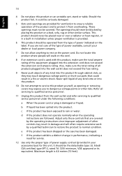
...provided for this product on the label. Maximum length is provided. 6 This product should be blocked by placing the product on the power cord. If you to normal condition. It should be operated from overheating. e If the product has been dropped or the case has...performance, indicating a need for service. 12 Use only the proper type of power supply cord set (provided in your accessories box) for ventilation to ensure reliable operation of power available, consult your dealer or local power company. 7 Do not allow anything to protect it could result in installation unless...
...provided for this product on the label. Maximum length is provided. 6 This product should be blocked by placing the product on the power cord. If you to normal condition. It should be operated from overheating. e If the product has been dropped or the case has...performance, indicating a need for service. 12 Use only the proper type of power supply cord set (provided in your accessories box) for ventilation to ensure reliable operation of power available, consult your dealer or local power company. 7 Do not allow anything to protect it could result in installation unless...


