

Power F1/ Aspire T310 Service Guide
Page 3
Revision History Please refer to the table below for the updates made on AcerPower F1/Aspire T310 service guide. 2003/10/29 Date 2003/12/18 Chapter 1 Chapter Chapter 1 Updates > Amend the FSB speed up to 800MHz on page 2 > Memory portion > Memory combination portion >Amend the Rear Panel and mainboard layout without SATA II
Revision History Please refer to the table below for the updates made on AcerPower F1/Aspire T310 service guide. 2003/10/29 Date 2003/12/18 Chapter 1 Chapter Chapter 1 Updates > Amend the FSB speed up to 800MHz on page 2 > Memory portion > Memory combination portion >Amend the Rear Panel and mainboard layout without SATA II
Power F1/ Aspire T310 Service Guide
Page 12
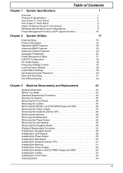
Table of Contents Chapter 1 System Specifications 1 Overview 1 Features & Specification 2 Acer Power F1 Front Panel 4 Acer Power F1 Rear Panel 5 Aspire T310/Acer Power F1 Front Panel 6 Hardware Specifications and Configurations 8 Power Management Function (ACPI support function 16 Chapter 2 System Utilities 17 Entering Setup 18 ... Daughter Board 50 Installing the LED Module 50 Installing the Power Button 50 Installing the Mainboard 50 Installing the Heatsink and the CPU 51 Installing the Memory 51 Installing the Power Supply 52 Installing the Modem card,CD-ROM, Floppy and...
Table of Contents Chapter 1 System Specifications 1 Overview 1 Features & Specification 2 Acer Power F1 Front Panel 4 Acer Power F1 Rear Panel 5 Aspire T310/Acer Power F1 Front Panel 6 Hardware Specifications and Configurations 8 Power Management Function (ACPI support function 16 Chapter 2 System Utilities 17 Entering Setup 18 ... Daughter Board 50 Installing the LED Module 50 Installing the Power Button 50 Installing the Mainboard 50 Installing the Heatsink and the CPU 51 Installing the Memory 51 Installing the Power Supply 52 Installing the Modem card,CD-ROM, Floppy and...

Power F1/ Aspire T310 Service Guide
Page 49
Options 36 Chapter 2 These items display the current status of all of the mainboard hardware devices/components such as CPU voltages, temperatures and all fans' speeds. When the processor reaches the temperature you set, the ACPI-aware system will be shut down. PC Health Status The following table describes the parameters found in this menu: Parameter Shutdown Temperature System Component Characteristics Description This option is for setting the shutdown temperature level for the processor.
Options 36 Chapter 2 These items display the current status of all of the mainboard hardware devices/components such as CPU voltages, temperatures and all fans' speeds. When the processor reaches the temperature you set, the ACPI-aware system will be shut down. PC Health Status The following table describes the parameters found in this menu: Parameter Shutdown Temperature System Component Characteristics Description This option is for setting the shutdown temperature level for the processor.
Power F1/ Aspire T310 Service Guide
Page 62
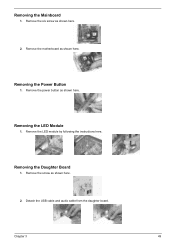
Removing the Mainboard 1. Removing the LED Module 1. Remove the LED module by following the instructions here. Detach the USB cable and audio cable from the daughter board. Remove the power button as shown here. 2. Remove the screw as shown here. Remove the six screw as shown here. Removing the Daughter Board 1. Removing the Power Button 1. Chapter 3 49 Remove the motherboard as shown here. 2.
Removing the Mainboard 1. Removing the LED Module 1. Remove the LED module by following the instructions here. Detach the USB cable and audio cable from the daughter board. Remove the power button as shown here. 2. Remove the screw as shown here. Remove the six screw as shown here. Removing the Daughter Board 1. Removing the Power Button 1. Chapter 3 49 Remove the motherboard as shown here. 2.

Power F1/ Aspire T310 Service Guide
Page 63
... shown here. Installing the Daughter Board 1. Fasten the daughter board with one screw as shown here. Put the motherboard to perform system service. Installing the Power Button 1. Standard Reassembly Procedure This section tells you how to reassemble the system when you need to the original position as shown here. 50 Chapter... the instructions here. Please also refer to the daughter board. 2. Connect the audio cable and USB cables to the assembly video, if available. Installing the Mainboard 1.
... shown here. Installing the Daughter Board 1. Fasten the daughter board with one screw as shown here. Put the motherboard to perform system service. Installing the Power Button 1. Standard Reassembly Procedure This section tells you how to reassemble the system when you need to the original position as shown here. 50 Chapter... the instructions here. Please also refer to the daughter board. 2. Connect the audio cable and USB cables to the assembly video, if available. Installing the Mainboard 1.

Power F1/ Aspire T310 Service Guide
Page 84
Chapter 5 Jumper and Connector Information Checking Jumper Settings This section explains how to set jumpers for correct configuration of the mainboard. Pins1 and 2 are placed on both pins, the jumper is placed on the correct pins. If you remove the jumper cap, or place... below show a 2-pin jumper. Jumpers with more than one pin, the jumper is OPEN. This illustration shows a 3-pin jumper. Setting Jumpers Use the mainboard jumpers to set system configuration options. When setting the jumpers, ensure that the jumper caps are SHORT. 1 23 Chapter 5 71 When the jumper cap is...
Chapter 5 Jumper and Connector Information Checking Jumper Settings This section explains how to set jumpers for correct configuration of the mainboard. Pins1 and 2 are placed on both pins, the jumper is placed on the correct pins. If you remove the jumper cap, or place... below show a 2-pin jumper. Jumpers with more than one pin, the jumper is OPEN. This illustration shows a 3-pin jumper. Setting Jumpers Use the mainboard jumpers to set system configuration options. When setting the jumpers, ensure that the jumper caps are SHORT. 1 23 Chapter 5 71 When the jumper cap is...

Power F1/ Aspire T310 Service Guide
Page 85
.... After updating the BIOS, return it to reset BIOS. This jumper enables you to update your mainboard from being updated (flashed). You may need to clear the CMOS memory if the settings in the Setup Utility are going to prevent the BIOS ...from operating. To clear the CMOS memory, disconnect all the power cables from the mainboard and then move the jumper cap into the CLEAR setting for a few seconds. This jumper enables you are incorrect that prevents your BIOS...
.... After updating the BIOS, return it to reset BIOS. This jumper enables you to update your mainboard from being updated (flashed). You may need to clear the CMOS memory if the settings in the Setup Utility are going to prevent the BIOS ...from operating. To clear the CMOS memory, disconnect all the power cables from the mainboard and then move the jumper cap into the CLEAR setting for a few seconds. This jumper enables you are incorrect that prevents your BIOS...

Power F1/ Aspire T310 Service Guide
Page 86
... 11 12 13 14 15 16 17 18 19 20 Signal Name +3.3V -12V Ground PS NO# Ground Ground Ground +5V +5V +5V ATX2: ATX12V Power Connector Pin 1 2 3 4 +12V +12V Ground Ground Signal Name Chapter 5 73 Connect the case switches and indicator LEDs to CPUFAN1. 2. Connect the CPU ...cooling fan cable to the PANEL1. 5. Connecting Case Components After you have installed the mainboard into a case, you can begin connecting the mainboard components. Refer to NBFAN1. 4. Connect the Northbridge cooling fna to the following: Description 1.
... 11 12 13 14 15 16 17 18 19 20 Signal Name +3.3V -12V Ground PS NO# Ground Ground Ground +5V +5V +5V ATX2: ATX12V Power Connector Pin 1 2 3 4 +12V +12V Ground Ground Signal Name Chapter 5 73 Connect the case switches and indicator LEDs to CPUFAN1. 2. Connect the CPU ...cooling fan cable to the PANEL1. 5. Connecting Case Components After you have installed the mainboard into a case, you can begin connecting the mainboard components. Refer to NBFAN1. 4. Connect the Northbridge cooling fna to the following: Description 1.

Power F1/ Aspire T310 Service Guide
Page 89
...AUD_FPOUT_R AUD_RET_R 7 HP_ON 8 KEY 9 AUD_FPOUT_L 10 AUD_RET_L Function Front Panel Microphone input signal Ground used by Analog Audio Circuits Microphone Power Filtered +5V used by Analog Audio Circuits Right Channel Audio signal to Front Panel Right Channel Audio signal to Return from Front ...Panel 76 Chapter 5 Connecting Optional Devices Refer to the following for information on connecting the mainboard's optional devices: AUDIO1: Front Panel Audio Connector This connector allows the user to Return from Front Panel Reserved for future use...
...AUD_FPOUT_R AUD_RET_R 7 HP_ON 8 KEY 9 AUD_FPOUT_L 10 AUD_RET_L Function Front Panel Microphone input signal Ground used by Analog Audio Circuits Microphone Power Filtered +5V used by Analog Audio Circuits Right Channel Audio signal to Front Panel Right Channel Audio signal to Return from Front ...Panel 76 Chapter 5 Connecting Optional Devices Refer to the following for information on connecting the mainboard's optional devices: AUDIO1: Front Panel Audio Connector This connector allows the user to Return from Front Panel Reserved for future use...

Power F1/ Aspire T310 Service Guide
Page 91
...NRIB Key Function Data Carry Detect Serial Data In Serial Data Out Data Terminal Ready Ground Data Set Ready Request to Send Clear to the mainboard. If you have USB ports at the front of case, use auxiliary USB connector to connect the front mounted ports to Send Ring Indicator... Panel USB Power USB Port 0 Negative Signal USB Port 1 Negative Signal USB Port 0 Positive Signal USB Port 1Positive Signal Ground Ground No Pin Overcurrent Signal NOTE: Please make sure that the USB cable has the same pin assignement as indicated above. USB3/USB4: Front Panel USB Connectors The mainboard has two...
...NRIB Key Function Data Carry Detect Serial Data In Serial Data Out Data Terminal Ready Ground Data Set Ready Request to Send Clear to the mainboard. If you have USB ports at the front of case, use auxiliary USB connector to connect the front mounted ports to Send Ring Indicator... Panel USB Power USB Port 0 Negative Signal USB Port 1 Negative Signal USB Port 0 Positive Signal USB Port 1Positive Signal Ground Ground No Pin Overcurrent Signal NOTE: Please make sure that the USB cable has the same pin assignement as indicated above. USB3/USB4: Front Panel USB Connectors The mainboard has two...

