
Service Guide
Page 7
... 12 Windows Keys 13 Special Key 14 Acer GridVista (dual-display compatible 15 Hardware Specifications and Configurations 16 System Utilities 23 BIOS Setup Utility 23 Navigating the BIOS Utility 23 Information 24 Main 25 Security 26 Boot 29 Exit 30 BIOS Flash Utility 31 Using the Flash16 Utility to Update the BIOS 31 WinFlash Utility 32 Remove HDD/BIOS Password Utilities 34 Miscellaneous Utilities 37 Machine Disassembly and Replacement 39 Disassembly Requirements 39 General Information 40 Pre-disassembly Instructions 40 Disassembly Process 40 External Module Disassembly...
... 12 Windows Keys 13 Special Key 14 Acer GridVista (dual-display compatible 15 Hardware Specifications and Configurations 16 System Utilities 23 BIOS Setup Utility 23 Navigating the BIOS Utility 23 Information 24 Main 25 Security 26 Boot 29 Exit 30 BIOS Flash Utility 31 Using the Flash16 Utility to Update the BIOS 31 WinFlash Utility 32 Remove HDD/BIOS Password Utilities 34 Miscellaneous Utilities 37 Machine Disassembly and Replacement 39 Disassembly Requirements 39 General Information 40 Pre-disassembly Instructions 40 Disassembly Process 40 External Module Disassembly...
Service Guide
Page 8
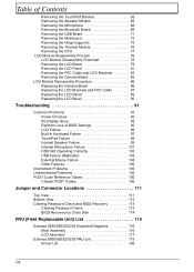
... 99 Internal Microphone Failure 101 HDD Not Operating Correctly 102 USB Failure (Rightside 103 External Mouse Failure 104 Other Failures 105 Intermittent Problems 105 Undetermined Problems 105 POST Code Reference Tables 106 Chipset POST Codes 106 Jumper and Connector Locations 111 Top View 111 Bottom View 112 Clearing Password Check and BIOS Recovery 113 Clearing Password Check 113 BIOS Recovery by Crisis Disk 114 FRU (Field Replaceable Unit) List 115 Extensa 5635/5635Z/5235 Exploded Diagrams...
... 99 Internal Microphone Failure 101 HDD Not Operating Correctly 102 USB Failure (Rightside 103 External Mouse Failure 104 Other Failures 105 Intermittent Problems 105 Undetermined Problems 105 POST Code Reference Tables 106 Chipset POST Codes 106 Jumper and Connector Locations 111 Top View 111 Bottom View 112 Clearing Password Check and BIOS Recovery 113 Clearing Password Check 113 BIOS Recovery by Crisis Disk 114 FRU (Field Replaceable Unit) List 115 Extensa 5635/5635Z/5235 Exploded Diagrams...

Service Guide
Page 15
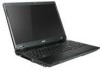
... audio output. Indicates when the hard disk drive is activated. Enables/disables the wireless LAN function. Power button Wireless LAN Communication button / Indicator Bluetooth Communication button/indicator Keyboard Turns the computer on and off. Enables/disables the Bluetooth function. Acer Notebook tour Front View No. 1 2 3 4 5 6 Chapter 1 Icon Item Acer Crystal Eye webcam Display screen Speakers HDD Num Lock Description Web camera for video communication (only for certain models) For entering data into your computer. 5 Caps Lock Lights up when Num Lock is active...
... audio output. Indicates when the hard disk drive is activated. Enables/disables the wireless LAN function. Power button Wireless LAN Communication button / Indicator Bluetooth Communication button/indicator Keyboard Turns the computer on and off. Enables/disables the Bluetooth function. Acer Notebook tour Front View No. 1 2 3 4 5 6 Chapter 1 Icon Item Acer Crystal Eye webcam Display screen Speakers HDD Num Lock Description Web camera for video communication (only for certain models) For entering data into your computer. 5 Caps Lock Lights up when Num Lock is active...

Service Guide
Page 17
... the screen brightness. + < > Brightness down Decreases the screen brightness. + < > Volume up Increases the sound volume. + < > Volume down Decreases the sound volume. Puts the computer in Sleep mode. + + + + Display toggle Screen blank TouchPad toggle Speaker toggle Switches display output between the display screen, external monitor (if connected) and both. Chapter 1 7 Press any given time. Turns the internal TouchPad on hotkeys + System Properties Display the System Properties dialog box. + + Power Options Sleep Display the Power Options...
... the screen brightness. + < > Brightness down Decreases the screen brightness. + < > Volume up Increases the sound volume. + < > Volume down Decreases the sound volume. Puts the computer in Sleep mode. + + + + Display toggle Screen blank TouchPad toggle Speaker toggle Switches display output between the display screen, external monitor (if connected) and both. Chapter 1 7 Press any given time. Turns the internal TouchPad on hotkeys + System Properties Display the System Properties dialog box. + + Power Options Sleep Display the Power Options...
Service Guide
Page 37
... on boot parameter. 5. When you are done, press F10 to enable the Password on the screen. 3. Use the ↑ and ↓ keys to "Clear". 4. The password length can opt to save the changes and exit the BIOS Setup Utility. Press Enter twice without typing anything in the "Enter New Password" field. If desired, you set the user or the supervisor password: 1. Retype the password in the Enter Current Password field and press Enter. 3. The Set Password...
... on boot parameter. 5. When you are done, press F10 to enable the Password on the screen. 3. Use the ↑ and ↓ keys to "Clear". 4. The password length can opt to save the changes and exit the BIOS Setup Utility. Press Enter twice without typing anything in the "Enter New Password" field. If desired, you set the user or the supervisor password: 1. Retype the password in the Enter Current Password field and press Enter. 3. The Set Password...

Service Guide
Page 38
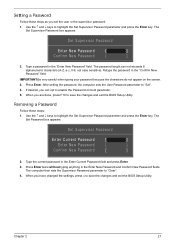
.... Type a password in the Enter Current Password field and press Enter. 3. If the verification is complete after the user presses Enter. When you can enable the Password on boot parameter. 6. The Set Password box appears. Retype the password in the Confirm New Password field. 4. Changing a Password 1. Set Supervisor Password Enter Current Password [ ] Enter New Password [ ] Confirm New Password [ ] 2. If desired, you are done, press F10 to save the changes and exit the BIOS Setup Utility. Use the ↑ and ↓ keys to "Set...
.... Type a password in the Enter Current Password field and press Enter. 3. If the verification is complete after the user presses Enter. When you can enable the Password on boot parameter. 6. The Set Password box appears. Retype the password in the Confirm New Password field. 4. Changing a Password 1. Set Supervisor Password Enter Current Password [ ] Enter New Password [ ] Confirm New Password [ ] 2. If desired, you are done, press F10 to save the changes and exit the BIOS Setup Utility. Use the ↑ and ↓ keys to "Set...

Service Guide
Page 39
... device fixed or removable. exclude or include the device to view or configure devices: Up and Down arrows select a device. Loads default boot sequence. Bootable devices includes USB drives, the onboard hard disk drive and the DVD drive in the module bay. and moves the device up or down. Boot This menu allows the user to decide the order of boot devices to load the operating system. Phoenix SecureCore(tm) Setup Utility Information Main Security Boot Exit Boot priority order: 1. PCI LAN...
... device fixed or removable. exclude or include the device to view or configure devices: Up and Down arrows select a device. Loads default boot sequence. Bootable devices includes USB drives, the onboard hard disk drive and the DVD drive in the module bay. and moves the device up or down. Boot This menu allows the user to decide the order of boot devices to load the operating system. Phoenix SecureCore(tm) Setup Utility Information Main Security Boot Exit Boot priority order: 1. PCI LAN...
Service Guide
Page 40
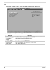
... all SETUP items. Save Setup Data to CMOS. F1 Help ESC Exit Select Item F5/F6 Change Values Select Menu Enter Execute Command F9 Setup Default F10 Save and Exit The table below describes the parameters in this screen. Exit utility without saving setup data to save or discard any changes you to CMOS. Exit The Exit screen allows you made and quit the BIOS Utility.
... all SETUP items. Save Setup Data to CMOS. F1 Help ESC Exit Select Item F5/F6 Change Values Select Menu Enter Execute Command F9 Setup Default F10 Save and Exit The table below describes the parameters in this screen. Exit utility without saving setup data to save or discard any changes you to CMOS. Exit The Exit screen allows you made and quit the BIOS Utility.
Service Guide
Page 41
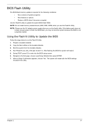
... BIOS flash memory update is not completely loaded. NOTE: Do not install memory-related drivers (XMS, EMS, DPMI) when you use the AC adaptor power supply when you may not boot the system because the BIOS is required for the following conditions: • New versions of system programs • New features or options • Restore a BIOS when it becomes corrupted. Run Phlash16.exe z06_3106.wph /mode=3 /x. When a Setup...
... BIOS flash memory update is not completely loaded. NOTE: Do not install memory-related drivers (XMS, EMS, DPMI) when you use the AC adaptor power supply when you may not boot the system because the BIOS is required for the following conditions: • New versions of system programs • New features or options • Restore a BIOS when it becomes corrupted. Run Phlash16.exe z06_3106.wph /mode=3 /x. When a Setup...

Service Guide
Page 63
Main Unit Disassembly Process Main Unit Disassembly Flowchart Remove External Modules before proceeding Remove Switch Cover Remove Keyboard Remove LCD Module Upper Cover Remove Upper Cover Remove TouchPad Bracket Remove Speaker Module Remove Microphone Lower Cover Remove Bluetooth Remove USB Board Remove Mainboard Remove Hinge Supports Remove Thermal Module Remove CPU Screw List Step Switch Cover LCD Module Upper Cover TouchPad Bracket Speaker Module Bluetooth Board USB Board Mainboard Hinge Supports Screw M2.5*2 M2.5*5 M2.5*5 M2.5*5 M2.5*4 M2.5*3 M2.5*3 M2*3 M2.5*5 M2.5*5 M2...
Main Unit Disassembly Process Main Unit Disassembly Flowchart Remove External Modules before proceeding Remove Switch Cover Remove Keyboard Remove LCD Module Upper Cover Remove Upper Cover Remove TouchPad Bracket Remove Speaker Module Remove Microphone Lower Cover Remove Bluetooth Remove USB Board Remove Mainboard Remove Hinge Supports Remove Thermal Module Remove CPU Screw List Step Switch Cover LCD Module Upper Cover TouchPad Bracket Speaker Module Bluetooth Board USB Board Mainboard Hinge Supports Screw M2.5*2 M2.5*5 M2.5*5 M2.5*5 M2.5*4 M2.5*3 M2.5*3 M2*3 M2.5*5 M2.5*5 M2...

Service Guide
Page 101
Obtain the failing symptoms in as much detail as a guide for computer problems. NOTE: The diagnostic tests are intended to test only Acer products. Symptoms (Verified) Go To Power On Issue No Display Issue LCD Failure Internal Keyboard Failure TouchPad Failure Internal Speaker Failure Internal Microphone Failure Right Side USB Failure Other Functions Failure Intermittent Problems Undetermined Problems Page 92 Page 93 Page 96 Page 97 Page...
Obtain the failing symptoms in as much detail as a guide for computer problems. NOTE: The diagnostic tests are intended to test only Acer products. Symptoms (Verified) Go To Power On Issue No Display Issue LCD Failure Internal Keyboard Failure TouchPad Failure Internal Speaker Failure Internal Microphone Failure Right Side USB Failure Other Functions Failure Intermittent Problems Undetermined Problems Page 92 Page 93 Page 96 Page 97 Page...

Service Guide
Page 103
... by removing the power cable and battery and holding down the power button for specific model procedures. 2. No Display Issue If the Display doesn't work, perform the following actions one at a time to correct the problem. 1. Reconnect the power and reboot the computer. 4. Remove any stored power by pressing Fn+F5. Reference Product pages for 10 seconds. Connect an external monitor to the computer and switch between the internal display and the external display...
... by removing the power cable and battery and holding down the power button for specific model procedures. 2. No Display Issue If the Display doesn't work, perform the following actions one at a time to correct the problem. 1. Reconnect the power and reboot the computer. 4. Remove any stored power by pressing Fn+F5. Reference Product pages for 10 seconds. Connect an external monitor to the computer and switch between the internal display and the external display...

Service Guide
Page 112
... "Disassembly Process" on the Boot menu. 6. Select Repair your computer. Select Startup Repair. i. Ensure all external devices. 2. Run Windows Check Disk by entering chkdsk /r from a known good date using up-to-date software to the operating system DVD. f. Check the BIOS settings are required. Run a complete virus scan using System Restore. b. The Install Windows screen displays. Click Next. e. The System Recovery Options screen displays. Click Next. Select the appropriate operating system, and click Next. NOTE: Click Load Drivers if controller drives...
... "Disassembly Process" on the Boot menu. 6. Select Repair your computer. Select Startup Repair. i. Ensure all external devices. 2. Run Windows Check Disk by entering chkdsk /r from a known good date using up-to-date software to the operating system DVD. f. Check the BIOS settings are required. Run a complete virus scan using System Restore. b. The Install Windows screen displays. Click Next. e. The System Recovery Options screen displays. Click Next. Select the appropriate operating system, and click Next. NOTE: Click Load Drivers if controller drives...
Service Guide
Page 114
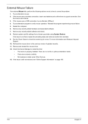
... device is properly installed. If the mouse uses a wireless connection, insert new batteries and confirm there is still not resolved, see Windows Help and Support. 10. Reinstall the program experiencing mouse failure. 5. If the Issue is a good connection. Remove any recently added hardware and associated software. 7. Restore system and file settings from a known good date using System Restore. Check the Device Manager to check the events log for errors. External Mouse Failure If an external Mouse...
... device is properly installed. If the mouse uses a wireless connection, insert new batteries and confirm there is still not resolved, see Windows Help and Support. 10. Reinstall the program experiencing mouse failure. 5. If the Issue is a good connection. Remove any recently added hardware and associated software. 7. Restore system and file settings from a known good date using System Restore. Check the Device Manager to check the events log for errors. External Mouse Failure If an external Mouse...
Service Guide
Page 115
...-Acer devices • Printer, mouse, and other external devices • Battery pack • Hard disk drive • DIMM • CD-ROM/Diskette drive Module • PC Cards 4. If any FRU. 3. Follow these procedures to Try. Visually check them for the system board in -1 Card Reader or Volume Wheel fail, perform the following general steps to do with a hardware defect, such as: cosmic radiation, electrostatic discharge, or software errors. If the problem...
...-Acer devices • Printer, mouse, and other external devices • Battery pack • Hard disk drive • DIMM • CD-ROM/Diskette drive Module • PC Cards 4. If any FRU. 3. Follow these procedures to Try. Visually check them for the system board in -1 Card Reader or Volume Wheel fail, perform the following general steps to do with a hardware defect, such as: cosmic radiation, electrostatic discharge, or software errors. If the problem...

Service Guide
Page 117
... vectors POST device initialization Check ROM copyright notice Check video configuration against CMOS Initialize PCI bus and devices Initialize all video adapters in system QuietBoot start (optional) Shadow video BIOS ROM Display BIOS copyright notice Display CPU type and speed Initialize EISA board Test keyboard Set key click if enabled Test for unexpected interrupts Initialize POST display service Display prompt Press F2 to enter SETUP Disable CPU cache Test RAM between 512 and 640 KB Test extended memory Test extended memory address lines...
... vectors POST device initialization Check ROM copyright notice Check video configuration against CMOS Initialize PCI bus and devices Initialize all video adapters in system QuietBoot start (optional) Shadow video BIOS ROM Display BIOS copyright notice Display CPU type and speed Initialize EISA board Test keyboard Set key click if enabled Test for unexpected interrupts Initialize POST display service Display prompt Press F2 to enter SETUP Disable CPU cache Test RAM between 512 and 640 KB Test extended memory Test extended memory address lines...

Service Guide
Page 118
... Extended BIOS Data Area Test and initialize PS/2 mouse Initialize floppy controller Determine number of ATA drives (optional) Initialize hard-disk controllers Initialize local-bus hard-disk controllers Jump to boot with INT 19 Initialize POST Error Manager (PEM) Initialize error logging Chapter 4 prepare to boot operating system One short beep before boot Terminate QuietBoot (optional) Check password (optional) Prepare Boot Initialize DMI parameters Initialize PnP Option ROMs Clear parity checkers Display MultiBoot menu Clear screen (optional) Check virus and backup reminders...
... Extended BIOS Data Area Test and initialize PS/2 mouse Initialize floppy controller Determine number of ATA drives (optional) Initialize hard-disk controllers Initialize local-bus hard-disk controllers Jump to boot with INT 19 Initialize POST Error Manager (PEM) Initialize error logging Chapter 4 prepare to boot operating system One short beep before boot Terminate QuietBoot (optional) Check password (optional) Prepare Boot Initialize DMI parameters Initialize PnP Option ROMs Clear parity checkers Display MultiBoot menu Clear screen (optional) Check virus and backup reminders...
Service Guide
Page 119
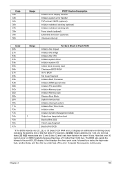
... I/O Check force recovery boot Checksum BIOS ROM Go to BIOS Set Huge Segment Initialize Multi Processor Initialize OEM special code Initialize PIC and DMA Initialize Memory type Initialize Memory size Shadow Boot Block System memory test Initialize interrupt vectors Initialize Run Time Clock Initialize video Initialize System Management Mode Output one beep before boot Boot to Mini DOS Clear Huge Segment Boot to the port-80 LED display. Chapter 4 109 Code C3h C4h...
... I/O Check force recovery boot Checksum BIOS ROM Go to BIOS Set Huge Segment Initialize Multi Processor Initialize OEM special code Initialize PIC and DMA Initialize Memory type Initialize Memory size Shadow Boot Block System memory test Initialize interrupt vectors Initialize Run Time Clock Initialize video Initialize System Management Mode Output one beep before boot Boot to Mini DOS Clear Huge Segment Boot to the port-80 LED display. Chapter 4 109 Code C3h C4h...

Service Guide
Page 197
...26 Boot 29 Exit 30 Navigating 23 Save and Exit 30 Security 26 System Security 30 Bluetooth Board Removing 69 Board Layout Top View 111 brightness hotkeys 7 C Camera Board Removing 85 Replacing 86 Common Problems 92 CPU Removing 77 D DIMM Modules Removing 50 Display 4 display hotkeys 7 E Euro 14 External Module Disassembly Flowchart 41 F Index Features 1 FLASH Utility 31 Flash Utility 31 FPC Cable Removing 83 FRU (Field Replaceable Unit) List 115 H Hard Disk Drive Module Removing 48 Hibernation mode hotkey 7 Hinge Supports Removing 75 Hot Keys 12 I Intermittent Problems 105 Internal Microphone...
...26 Boot 29 Exit 30 Navigating 23 Save and Exit 30 Security 26 System Security 30 Bluetooth Board Removing 69 Board Layout Top View 111 brightness hotkeys 7 C Camera Board Removing 85 Replacing 86 Common Problems 92 CPU Removing 77 D DIMM Modules Removing 50 Display 4 display hotkeys 7 E Euro 14 External Module Disassembly Flowchart 41 F Index Features 1 FLASH Utility 31 Flash Utility 31 FPC Cable Removing 83 FRU (Field Replaceable Unit) List 115 H Hard Disk Drive Module Removing 48 Hibernation mode hotkey 7 Hinge Supports Removing 75 Hot Keys 12 I Intermittent Problems 105 Internal Microphone...

Service Guide
Page 198
... Battery Removing 45 S SD Dummy Card Removing 43 Speaker Module Removing 65 speakers hotkey 7 Switch Cover Removing 54 System Block Diagram 4 T Test Compatible Components 179 Thermal Module Removing 76 Top 111 Touch Pad hotkey 7 Touch Pad Failure 98 TouchPad Bracket Removing 63 Troubleshooting Built-in KB Failure 97 Internal Microphone 101 Internal Speakers 99 LCD Failure 96 No Display 93 ODD 103, 104 Other Failures 105 Power Button 104 Power On 92 Touch Pad 98 USB 103 WLAN 104 U Undetermined Problems 105 Upper Cover Removing...
... Battery Removing 45 S SD Dummy Card Removing 43 Speaker Module Removing 65 speakers hotkey 7 Switch Cover Removing 54 System Block Diagram 4 T Test Compatible Components 179 Thermal Module Removing 76 Top 111 Touch Pad hotkey 7 Touch Pad Failure 98 TouchPad Bracket Removing 63 Troubleshooting Built-in KB Failure 97 Internal Microphone 101 Internal Speakers 99 LCD Failure 96 No Display 93 ODD 103, 104 Other Failures 105 Power Button 104 Power On 92 Touch Pad 98 USB 103 WLAN 104 U Undetermined Problems 105 Upper Cover Removing...


