Altos G310 Service Guide
Page 1
Altos G310 Service Guide Service guide files and updates are available on the CSD web; for more information, please refer to http://csd.acer.com.tw PART NO.: VD.G31VF.001 PRINTED IN TAIWAN
Altos G310 Service Guide Service guide files and updates are available on the CSD web; for more information, please refer to http://csd.acer.com.tw PART NO.: VD.G31VF.001 PRINTED IN TAIWAN
Altos G310 Service Guide
Page 2
Revision History Please refer to the table below for the updates made on page 27. Product Information on Altos G310 service guide. II Date 2004/06/18 Chapter CH2 Updates update the BIOS Screen --
Revision History Please refer to the table below for the updates made on page 27. Product Information on Altos G310 service guide. II Date 2004/06/18 Chapter CH2 Updates update the BIOS Screen --
Altos G310 Service Guide
Page 7
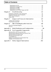
... Beep Codes 67 Chapter 5 Jumper and Connector Information 68 Jumpers and Connectors 68 Front Panel I/O and LED 74 Chapter 6 FRU (Field Replaceable Unit) List 80 Altos G310 Exploded Diagram 81 Part List 82 Appendix A Model Definition and Configuration 86 Appendix B Test Compatible Components 87 Windows NT4.0+SP6 Environment Test 88 Windows 2000...
... Beep Codes 67 Chapter 5 Jumper and Connector Information 68 Jumpers and Connectors 68 Front Panel I/O and LED 74 Chapter 6 FRU (Field Replaceable Unit) List 80 Altos G310 Exploded Diagram 81 Part List 82 Appendix A Model Definition and Configuration 86 Appendix B Test Compatible Components 87 Windows NT4.0+SP6 Environment Test 88 Windows 2000...
Altos G310 Service Guide
Page 11
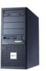
Front Bezel No. 1 2 3 4 5 6 7 8 9 10 11 12 13 CD-ROM Drive CD-ROM Headphone Port CD-ROM Volume Control CD-ROM Activity Indicator FDD Eject Button FDD (Floppy Disc Drive) FDD Activity Indicator Security Keylock System Power Indicator System Power Button USB 2.0 Ports (two) 5.25-inch half-height bays CD-ROM stop/eject button Item 4 Altos G310
Front Bezel No. 1 2 3 4 5 6 7 8 9 10 11 12 13 CD-ROM Drive CD-ROM Headphone Port CD-ROM Volume Control CD-ROM Activity Indicator FDD Eject Button FDD (Floppy Disc Drive) FDD Activity Indicator Security Keylock System Power Indicator System Power Button USB 2.0 Ports (two) 5.25-inch half-height bays CD-ROM stop/eject button Item 4 Altos G310
Altos G310 Service Guide
Page 13
Rear Panel No. 1 2 3 4 5 6 7 8 9 10 11 Item Main Power Supply Unit PS/2 Mouse Port PS/2 Keyboard Port Parallel/Printer Port Serial Ports (two) USB 2.0 Ports (four) Gigabit LAN Port (10/100/1000 Mbps) AGP Add-On Card (actual ports vary by configuration) Side panel tool-less screws (top and bottom) System venitlation/fan exhaust Main power supply fan-exhaust 6 Altos G310
Rear Panel No. 1 2 3 4 5 6 7 8 9 10 11 Item Main Power Supply Unit PS/2 Mouse Port PS/2 Keyboard Port Parallel/Printer Port Serial Ports (two) USB 2.0 Ports (four) Gigabit LAN Port (10/100/1000 Mbps) AGP Add-On Card (actual ports vary by configuration) Side panel tool-less screws (top and bottom) System venitlation/fan exhaust Main power supply fan-exhaust 6 Altos G310
Altos G310 Service Guide
Page 19
... Depends on CPU, which is booting to systems installed with a Pentium III processor. L2 Cache RAM speed Full of the processor core clock frequency (Advanced Transfer Cache) L2 Cache function control Enable/disable by BIOS Setup Second-Level Cache...Configurations The information below is recommended that you AVOID using modules from different manufacturers or that run at different speeds from each other. 12 Altos G310 Cache Memory Item Specification First-Level Cache Configurations Cache function control Enable/disable by BIOS Setup L2 Cache scheme Fixed in write-back VRD...
... Depends on CPU, which is booting to systems installed with a Pentium III processor. L2 Cache RAM speed Full of the processor core clock frequency (Advanced Transfer Cache) L2 Cache function control Enable/disable by BIOS Setup Second-Level Cache...Configurations The information below is recommended that you AVOID using modules from different manufacturers or that run at different speeds from each other. 12 Altos G310 Cache Memory Item Specification First-Level Cache Configurations Cache function control Enable/disable by BIOS Setup L2 Cache scheme Fixed in write-back VRD...
Altos G310 Service Guide
Page 21
...-00D7FFF 00D8000-00DBFFF 00DC000-00DFFFF 00E0000-00E7FFF 00E8000-00EFFFF 00F0000-00FFFFF 0100000-0F9FFFF 0FA0000-0FFFFFF 1000000-FFFFFFF Size 640 KB System Memory 128 KB Video RAM 32 KB I/O Expansion ROM 16 KB I/O Expansion ROM 16 KB I/O Expansion ROM 16 KB I/O Expansion ROM 16 KB I/O Expansion ROM 32 KB for SCSI BIOS... for ROM on I/O Adapters Reserved for ROM on I/O Adapters Reserved for ROM on I/O Adapters Reserved for SCSI BIOS Reserved Onboard System ROM BIOS (ROM) System RAM BIOS (DRAM) Onboard DRAM Reserved for Memory Map I/O Card Non-Cacheable Onboard DRAM 14...
...-00D7FFF 00D8000-00DBFFF 00DC000-00DFFFF 00E0000-00E7FFF 00E8000-00EFFFF 00F0000-00FFFFF 0100000-0F9FFFF 0FA0000-0FFFFFF 1000000-FFFFFFF Size 640 KB System Memory 128 KB Video RAM 32 KB I/O Expansion ROM 16 KB I/O Expansion ROM 16 KB I/O Expansion ROM 16 KB I/O Expansion ROM 16 KB I/O Expansion ROM 32 KB for SCSI BIOS... for ROM on I/O Adapters Reserved for ROM on I/O Adapters Reserved for ROM on I/O Adapters Reserved for SCSI BIOS Reserved Onboard System ROM BIOS (ROM) System RAM BIOS (DRAM) Onboard DRAM Reserved for Memory Map I/O Card Non-Cacheable Onboard DRAM 14...
Altos G310 Service Guide
Page 23
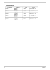
PCI Interrupt Routing PCI Devices PCI Slot 1 PCI Slot 2 PCI Slot 3 PCI Slot 4 PCI Slot 5 REQ#/GNT# P_REQ#1 P_GNT#1 P_REQ#2 P_GNT#2 P_REQ#3 P_GNT#3 P_REQ#4 P_GNT#4 P_REQ#5 P_GNT#5 IDSEL D_AD17 D_AD18 D_AD19 D_AD20 D_AD21 Others From SB / PCI Slot From SB / PCI Slot From SB / PCI Slot From SB / PCI Slot From SB / PCI Slot 16 Altos G310
PCI Interrupt Routing PCI Devices PCI Slot 1 PCI Slot 2 PCI Slot 3 PCI Slot 4 PCI Slot 5 REQ#/GNT# P_REQ#1 P_GNT#1 P_REQ#2 P_GNT#2 P_REQ#3 P_GNT#3 P_REQ#4 P_GNT#4 P_REQ#5 P_GNT#5 IDSEL D_AD17 D_AD18 D_AD19 D_AD20 D_AD21 Others From SB / PCI Slot From SB / PCI Slot From SB / PCI Slot From SB / PCI Slot From SB / PCI Slot 16 Altos G310
Altos G310 Service Guide
Page 25
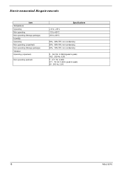
Environmental Requirements Item Temperature Operating Non-operating Non-operating (Storage package) Humidity Operating Non-operating (unpacked) Non-operating (Storage package) Vibration Operating (unpacked) Non-operating (packed) Specifications +10 to +35°C -10 to +60°C -20 to +60°C 20% - 80% RH, non-condensing 20% - 80% RH, non-condensing 20% - 90% RH, non-condensing 5 - 16.2 Hz: 0.38mm(peak to peak) 16.2 - 250 Hz: 0.2G 5 - 27.1 Hz: 0.60G 27.1 - 50 Hz: 0.4mm (peak to peak) 50 - 500 Hz: 2.0G 18 Altos G310
Environmental Requirements Item Temperature Operating Non-operating Non-operating (Storage package) Humidity Operating Non-operating (unpacked) Non-operating (Storage package) Vibration Operating (unpacked) Non-operating (packed) Specifications +10 to +35°C -10 to +60°C -20 to +60°C 20% - 80% RH, non-condensing 20% - 80% RH, non-condensing 20% - 90% RH, non-condensing 5 - 16.2 Hz: 0.38mm(peak to peak) 16.2 - 250 Hz: 0.2G 5 - 27.1 Hz: 0.60G 27.1 - 50 Hz: 0.4mm (peak to peak) 50 - 500 Hz: 2.0G 18 Altos G310
Altos G310 Service Guide
Page 27
ASM-Console- the individual servers managed by the ASM-Consol 20 Altos G310 ASM ASM 6.0 ASM is designed primarily for server supervisors and management information system (MIS) personnel to the processor thermal condition, voltage detection, fan status or ...
ASM-Console- the individual servers managed by the ASM-Consol 20 Altos G310 ASM ASM 6.0 ASM is designed primarily for server supervisors and management information system (MIS) personnel to the processor thermal condition, voltage detection, fan status or ...

Altos G310 Service Guide
Page 35
It is stored in SMBIOS table: "Type 1:offset 08h 00000000000000000000 Baseboard identification. Altos XXXX Unique ID. Display the string that is flashed at factory and would be updated by SMBIOS update utility. It is stored in SMBIOS table "...
It is stored in SMBIOS table: "Type 1:offset 08h 00000000000000000000 Baseboard identification. Altos XXXX Unique ID. Display the string that is flashed at factory and would be updated by SMBIOS update utility. It is stored in SMBIOS table "...
Altos G310 Service Guide
Page 57
Unplug the power cable from the system. 49 Altos G310 Turn off the power to the system and all peripherals. 2. General Information Before You Begin Before proceeding with the disassembly procedure, make sure that you do the following: 1.
Unplug the power cable from the system. 49 Altos G310 Turn off the power to the system and all peripherals. 2. General Information Before You Begin Before proceeding with the disassembly procedure, make sure that you do the following: 1.
Altos G310 Service Guide
Page 59
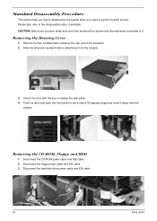
Disconnect the hard disk drive power cable and IDE cable 51 Altos G310 Removing the Housing Cover 1. Unlock the door with the key to the disassembly video, if available. Push the latch and open the front panel to ...
Disconnect the hard disk drive power cable and IDE cable 51 Altos G310 Removing the Housing Cover 1. Unlock the door with the key to the disassembly video, if available. Push the latch and open the front panel to ...
Altos G310 Service Guide
Page 61
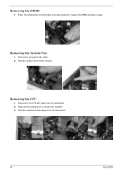
Disconnect the system fan cable. 2. Removing the CPU 1. Take the system fan from the mainboard 2. Disconnect the CPU fan cable from the chassis. Press the holding clips on both sides of socket outward to release the heatsink. 3. Take the heatsink module away from the mainboard. 53 Altos G310 Removing the System Fan 1. Removing the DIMM 1. Depress the locking lever to release the DIMM and take it away.
Disconnect the system fan cable. 2. Removing the CPU 1. Take the system fan from the mainboard 2. Disconnect the CPU fan cable from the chassis. Press the holding clips on both sides of socket outward to release the heatsink. 3. Take the heatsink module away from the mainboard. 53 Altos G310 Removing the System Fan 1. Removing the DIMM 1. Depress the locking lever to release the DIMM and take it away.
Altos G310 Service Guide
Page 63
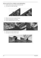
Take the module away from the chassis. 6. Then take the lock switch cable away. 3. Remove the two screws to release the module. 4. Take the USB module away from the chassis. 5. Then take the lock away from the chassis. 55 Altos G310 Removing the Power Button and USB Modules 1. Remove the two screws to release the lock switch cable. 2. Remove the one screw to release the lock. 7.
Take the module away from the chassis. 6. Then take the lock switch cable away. 3. Remove the two screws to release the module. 4. Take the USB module away from the chassis. 5. Then take the lock away from the chassis. 55 Altos G310 Removing the Power Button and USB Modules 1. Remove the two screws to release the lock switch cable. 2. Remove the one screw to release the lock. 7.
Altos G310 Service Guide
Page 65
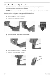
... it . Place the USB board module to it . 4. Secure the one screw to the bracket. 7. Place the power button module to fasten the board. 57 Altos G310 Reconnect the USB cable to the USB board. 2.
... it . Place the USB board module to it . 4. Secure the one screw to the bracket. 7. Place the power button module to fasten the board. 57 Altos G310 Reconnect the USB cable to the USB board. 2.
Altos G310 Service Guide
Page 67
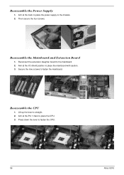
Reassemble the Power Supply 1. Aim at the I/O shield position to place the mainboard with caution. 3. Reconnect the extension daughter board to fasten the mainboard. Aim at the track to place the power supply to place the CPU. 3. Secure the nine screws to the mainboard. 2. Lift up the lever to fasten the CPU. 59 Altos G310 Press down the lever to straight. 2. Reassemble the Mainboard and Extension Board 1. Then secure the four screws. Reassemble the CPU 1. Aim at the Pin 1 mark to the chassis. 2.
Reassemble the Power Supply 1. Aim at the I/O shield position to place the mainboard with caution. 3. Reconnect the extension daughter board to fasten the mainboard. Aim at the track to place the power supply to place the CPU. 3. Secure the nine screws to the mainboard. 2. Lift up the lever to fasten the CPU. 59 Altos G310 Press down the lever to straight. 2. Reassemble the Mainboard and Extension Board 1. Then secure the four screws. Reassemble the CPU 1. Aim at the Pin 1 mark to the chassis. 2.
Altos G310 Service Guide
Page 69
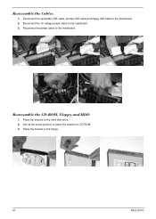
Aim at the screw position to the mainboard. Reconnect the power cable to place the bracket on CD-ROM. 3. Place the bracket to the mainboard. 2. Reassemble the CD-ROM, Floppy and HDD 1. Reconnect the secondary IDE cable, primary IDE cable and floppy IDE cable to the floppy. 61 Altos G310 Reassemble the Cables 1. Reconnect the 12 voltage power cable to the hard disk drive. 2. Place the bracket to the mainboard. 3.
Aim at the screw position to the mainboard. Reconnect the power cable to place the bracket on CD-ROM. 3. Place the bracket to the mainboard. 2. Reassemble the CD-ROM, Floppy and HDD 1. Reconnect the secondary IDE cable, primary IDE cable and floppy IDE cable to the floppy. 61 Altos G310 Reassemble the Cables 1. Reconnect the 12 voltage power cable to the hard disk drive. 2. Place the bracket to the mainboard. 3.
Altos G310 Service Guide
Page 72
POST Code Checkpoints ! Troubleshooting This chapter provides troubleshooting information for the Altos G310: ! Beep Codes Chapter 4 Chapter 4 62 Bootblock Initialization Code Checkpoints ! Bootblock Recovery Code Checkpoints !
POST Code Checkpoints ! Troubleshooting This chapter provides troubleshooting information for the Altos G310: ! Beep Codes Chapter 4 Chapter 4 62 Bootblock Initialization Code Checkpoints ! Bootblock Recovery Code Checkpoints !
Altos G310 Service Guide
Page 73
... bootblock checksum. Determine whether to it . Store the Uncompressed pointer for future use in scratch CMOS. Leaves all RAM below 1MB Read-Write including E000 and F000 shadow areas but closing SMRAM. NIMI is tested. Disable CACHE before... memory detection. Save power-on CPUID value in PMM. Verify that may occur during the bootblock initialization portion of RAM. If memory sizing module not executed, start memory refresh and do memory sizing in memory. Re-enable CACHE. ... controller. CPUID information is enabled. Give control to BIOS POST. 63 Altos G310
... bootblock checksum. Determine whether to it . Store the Uncompressed pointer for future use in scratch CMOS. Leaves all RAM below 1MB Read-Write including E000 and F000 shadow areas but closing SMRAM. NIMI is tested. Disable CACHE before... memory detection. Save power-on CPUID value in PMM. Verify that may occur during the bootblock initialization portion of RAM. If memory sizing module not executed, start memory refresh and do memory sizing in memory. Re-enable CACHE. ... controller. CPUID information is enabled. Give control to BIOS POST. 63 Altos G310

