
User Manual
Page 6
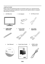
UNPACKING Please check the following items are present when you unpack the box, and save the packing materials in case you will need to ship or transport the monitor in future. LCD Monitor AC Adapter AC Power Cord · Audio Cable (Optional) D-Sub Cable (Optional) DVI Cable (Optional) User Manual G196WL G206HL G226HQL G236HL LCD monitor MU.LUZ00.001 Quick Start Guide HDMI cable (Optional) G196WL EN-5
UNPACKING Please check the following items are present when you unpack the box, and save the packing materials in case you will need to ship or transport the monitor in future. LCD Monitor AC Adapter AC Power Cord · Audio Cable (Optional) D-Sub Cable (Optional) DVI Cable (Optional) User Manual G196WL G206HL G226HQL G236HL LCD monitor MU.LUZ00.001 Quick Start Guide HDMI cable (Optional) G196WL EN-5
User Manual
Page 8
...220/240 V AC voltage area. The cord set should have the appropriate safety approvals for your area. · This monitor has a universal power supply that the power cord you use is adequate ventilation. · Avoid placing the monitor against a bright background or where sun- Place the monitor just below ...Plug one end of the monitor. SAFETY PRECAUTION · Avoid placing the monitor, or any other light sources may reflect on the power cord to avoid damage to the cable. · Do not expose the monitor to rain, excessive moisture, or dust. · Do not cover the ventilation slots or...
...220/240 V AC voltage area. The cord set should have the appropriate safety approvals for your area. · This monitor has a universal power supply that the power cord you use is adequate ventilation. · Avoid placing the monitor against a bright background or where sun- Place the monitor just below ...Plug one end of the monitor. SAFETY PRECAUTION · Avoid placing the monitor, or any other light sources may reflect on the power cord to avoid damage to the cable. · Do not expose the monitor to rain, excessive moisture, or dust. · Do not cover the ventilation slots or...
User Manual
Page 10
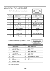
DESCRIPTION +5V Logic Ground Monitor Ground DDC-Serial Data H-Sync V-Sync DDC-Serial Clock 19-pin Color Display Signal Cable* 1917151311 9 7 5 3 1 1816141210 8 6 4 2 PIN No. Description 2 TMDS Data2 Shield 4 TMDS Data1+ 6 TMDS Data1- 8 TMDS Data0 Shield 10 TMDS Clock+ 12 ...R-Ground G-Ground B-Ground PIN NO. 9. 10. 11. 12. 13. 14. 15. CONNECTOR PIN ASSIGNMENT 15-Pin Color Display Signal Cable PIN NO. 1. 2. 3. 4. 5. 6. 7. 8. on device) 16 SDA 18 +5V Power * only for certain models EN-9 Description 1 TMDS Data2+ 3 TMDS Data2- 5 TMDS Data1 Shield 7 TMDS Data0+ 9 TMDS Data0...
DESCRIPTION +5V Logic Ground Monitor Ground DDC-Serial Data H-Sync V-Sync DDC-Serial Clock 19-pin Color Display Signal Cable* 1917151311 9 7 5 3 1 1816141210 8 6 4 2 PIN No. Description 2 TMDS Data2 Shield 4 TMDS Data1+ 6 TMDS Data1- 8 TMDS Data0 Shield 10 TMDS Clock+ 12 ...R-Ground G-Ground B-Ground PIN NO. 9. 10. 11. 12. 13. 14. 15. CONNECTOR PIN ASSIGNMENT 15-Pin Color Display Signal Cable PIN NO. 1. 2. 3. 4. 5. 6. 7. 8. on device) 16 SDA 18 +5V Power * only for certain models EN-9 Description 1 TMDS Data2+ 3 TMDS Data2- 5 TMDS Data1 Shield 7 TMDS Data0+ 9 TMDS Data0...
User Manual
Page 11
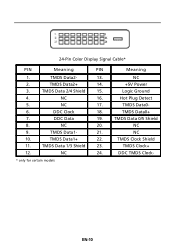
24-Pin Color Display Signal Cable* PIN Meaning PIN Meaning 1. Logic Ground 4. NC 17. NC 10. TMDS Clock+ 12. NC 2. TMDS Data 2/4 Shield 15. TMDS Data0+ 7. NC 9. NC 16. DDC Data 19. TMDS Data1- 21. TMDS Data1+ 22. DDC TMDS Clock- * only for certain models EN-10 NC 20. NC 24. TMDS Data2+ 14. +5V Power 3. Hot Plug Detect 5. DDC Clock 18. TMDS Clock Shield 11. TMDS Data 0/5 Shield 8. TMDS Data0- 6. TMDS Data 1/3 Shield 23. TMDS Data2- 13.
24-Pin Color Display Signal Cable* PIN Meaning PIN Meaning 1. Logic Ground 4. NC 17. NC 10. TMDS Clock+ 12. NC 2. TMDS Data 2/4 Shield 15. TMDS Data0+ 7. NC 9. NC 16. DDC Data 19. TMDS Data1- 21. TMDS Data1+ 22. DDC TMDS Clock- * only for certain models EN-10 NC 20. NC 24. TMDS Data2+ 14. +5V Power 3. Hot Plug Detect 5. DDC Clock 18. TMDS Clock Shield 11. TMDS Data 0/5 Shield 8. TMDS Data0- 6. TMDS Data 1/3 Shield 23. TMDS Data2- 13.
User Manual
Page 15
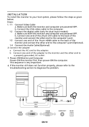
... the AC cord to your host system, please follow the steps as given below: Steps 1. 1-1 Connect Video Cable a. Power-ON Monitor and Computer Power-ON the monitor first, then power-ON the computer. This sequence is very important. 4. Mnnaekcet stuhreedbiogtithatlhceabmleo(noitnolyr afonrddcuoaml-pinupteurt amreodpeolws).ered-OFF. Connect one...VGA DVI D-SUB DC AUDIO OUT DC-IN EN-14 b. Make sure both the monitor and computer are powered-OFF. b. b Connect one end of the 19-pin HDMI cable to the back of the adapter to the monitor and the other end to a properly grounded, AC outlet ...
... the AC cord to your host system, please follow the steps as given below: Steps 1. 1-1 Connect Video Cable a. Power-ON Monitor and Computer Power-ON the monitor first, then power-ON the computer. This sequence is very important. 4. Mnnaekcet stuhreedbiogtithatlhceabmleo(noitnolyr afonrddcuoaml-pinupteurt amreodpeolws).ered-OFF. Connect one...VGA DVI D-SUB DC AUDIO OUT DC-IN EN-14 b. Make sure both the monitor and computer are powered-OFF. b. b Connect one end of the 19-pin HDMI cable to the back of the adapter to the monitor and the other end to a properly grounded, AC outlet ...
User Manual
Page 16
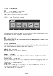
...button to set the HPos, VPos, Clock and Focus. The Auto Adjustment function is used to open the Acer eColor Management OSD and access the scenario modes. INPUT Input Key Use Input key to select from different .... MENU OSD functions Press this button to appear. Lights up to activate the OSD menu. USER CONTROLS Power Switch / Power LED: To turn the monitor ON or OFF. It may be connected to your monitor. (a) VGA ... settings. AUTO Auto Adjust: Press this botton to indicate the power is selected ,but the VGA and DVI cables are not connected, a floating dialog box indicates: "No...
...button to set the HPos, VPos, Clock and Focus. The Auto Adjustment function is used to open the Acer eColor Management OSD and access the scenario modes. INPUT Input Key Use Input key to select from different .... MENU OSD functions Press this button to appear. Lights up to activate the OSD menu. USER CONTROLS Power Switch / Power LED: To turn the monitor ON or OFF. It may be connected to your monitor. (a) VGA ... settings. AUTO Auto Adjust: Press this botton to indicate the power is selected ,but the VGA and DVI cables are not connected, a floating dialog box indicates: "No...
User Manual
Page 22
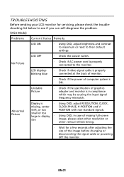
... of the image before changing or disconnecting the signal cable or powering OFF the monitor. EN-21 LED displays blinking blue · Check if video signal cable is properly connected at the back of monitor. · Check if the power of graphics adapter and monitor is ON. Abnormal Picture... Display is properly connected to their default settings. LED OFF · Check the power switch. No Picture · Check...
... of the image before changing or disconnecting the signal cable or powering OFF the monitor. EN-21 LED displays blinking blue · Check if video signal cable is properly connected at the back of monitor. · Check if the power of graphics adapter and monitor is ON. Abnormal Picture... Display is properly connected to their default settings. LED OFF · Check the power switch. No Picture · Check...
User Manual
Page 23
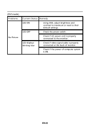
EN-22 (DVI mode) Problems No Picture Current Status Remedy LED ON · Using OSD, adjust brightness and contrast to maximum or reset to the monitor. LED displays blinking blue · Check if video signal cable is properly connected at the back of monitor. · Check if the power of computer system is properly connected to their default settings. LED OFF · Check the power switch. · Check if AC power cord is ON.
EN-22 (DVI mode) Problems No Picture Current Status Remedy LED ON · Using OSD, adjust brightness and contrast to maximum or reset to the monitor. LED displays blinking blue · Check if video signal cable is properly connected at the back of monitor. · Check if the power of computer system is properly connected to their default settings. LED OFF · Check the power switch. · Check if AC power cord is ON.


