
User Manual
Page 9
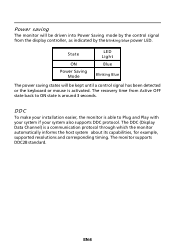
The recovery time from the display controller, as indicated by the control signal from Active OFF state back to Plug and Play with your system if your system also supports DDC protocol. The DDC (Display Data Channel) is ... by the blinking blue power LED. State ON Power Saving Mode LED Light Blue Blinking Blue The power saving states will be kept until a control signal has been detected or the keyboard or mouse is around 3 seconds.
The recovery time from the display controller, as indicated by the control signal from Active OFF state back to Plug and Play with your system if your system also supports DDC protocol. The DDC (Display Data Channel) is ... by the blinking blue power LED. State ON Power Saving Mode LED Light Blue Blinking Blue The power saving states will be kept until a control signal has been detected or the keyboard or mouse is around 3 seconds.
User Manual
Page 10
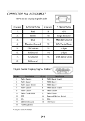
...- 11 TMDS Clock Shield 13 CEC 15 SCL 17 DDC/CEC Ground 19 Hot Plug Detect PIN No. CONNECTOR PIN ASSIGNMENT 15-Pin Color Display Signal Cable PIN NO. 1. 2. 3. 4. 5. 6. 7. 8. DESCRIPTION Red Green Blue Monitor Ground DDC-return R-Ground G-Ground B-Ground PIN NO. 9. 10. 11. 12. 13. 14. 15. DESCRIPTION +5V Logic... Ground Monitor Ground DDC-Serial Data H-Sync V-Sync DDC-Serial Clock 19-pin Color Display Signal Cable* 1917151311 9 7 5 3 1 1816141210 8 6 4 2 PIN No. on device) 16 SDA 18 +5V Power * only for certain models EN-9
...- 11 TMDS Clock Shield 13 CEC 15 SCL 17 DDC/CEC Ground 19 Hot Plug Detect PIN No. CONNECTOR PIN ASSIGNMENT 15-Pin Color Display Signal Cable PIN NO. 1. 2. 3. 4. 5. 6. 7. 8. DESCRIPTION Red Green Blue Monitor Ground DDC-return R-Ground G-Ground B-Ground PIN NO. 9. 10. 11. 12. 13. 14. 15. DESCRIPTION +5V Logic... Ground Monitor Ground DDC-Serial Data H-Sync V-Sync DDC-Serial Clock 19-pin Color Display Signal Cable* 1917151311 9 7 5 3 1 1816141210 8 6 4 2 PIN No. on device) 16 SDA 18 +5V Power * only for certain models EN-9
User Manual
Page 11
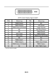
Logic Ground 4. TMDS Data0- 6. DDC Clock 18. DDC Data 19. NC 9. TMDS Data1+ 22. TMDS Clock+ 12. Hot Plug Detect 5. NC 20. DDC TMDS Clock- * only for certain models EN-10 TMDS Data2- 13. NC 17. TMDS Data 1/3 Shield 23. NC 2. TMDS Data1- 21. TMDS Clock Shield 11. TMDS Data2+ 14. +5V Power 3. NC 16. NC 10. TMDS Data 2/4 Shield 15. 24-Pin Color Display Signal Cable* PIN Meaning PIN Meaning 1. TMDS Data0+ 7. TMDS Data 0/5 Shield 8. NC 24.
Logic Ground 4. TMDS Data0- 6. DDC Clock 18. DDC Data 19. NC 9. TMDS Data1+ 22. TMDS Clock+ 12. Hot Plug Detect 5. NC 20. DDC TMDS Clock- * only for certain models EN-10 TMDS Data2- 13. NC 17. TMDS Data 1/3 Shield 23. NC 2. TMDS Data1- 21. TMDS Clock Shield 11. TMDS Data2+ 14. +5V Power 3. NC 16. NC 10. TMDS Data 2/4 Shield 15. 24-Pin Color Display Signal Cable* PIN Meaning PIN Meaning 1. TMDS Data0+ 7. TMDS Data 0/5 Shield 8. NC 24.
User Manual
Page 16
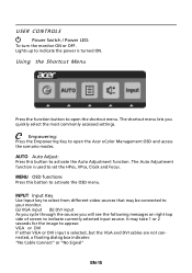
... image to indicate the power is selected ,but the VGA and DVI cables are not connected, a floating dialog box indicates: "No Cable Connect" or "No Signal" EN-15 USER CONTROLS Power Switch / Power LED: To turn the monitor ON or OFF. Using the Shortcut Menu Press the function button to set... the HPos, VPos, Clock and Focus. The Auto Adjustment function is used to open the Acer eColor Management OSD and access the scenario modes. VGA or DVI If either VGA or DVI input is turned ON. Lights up to appear. It...
... image to indicate the power is selected ,but the VGA and DVI cables are not connected, a floating dialog box indicates: "No Cable Connect" or "No Signal" EN-15 USER CONTROLS Power Switch / Power LED: To turn the monitor ON or OFF. Using the Shortcut Menu Press the function button to set... the HPos, VPos, Clock and Focus. The Auto Adjustment function is used to open the Acer eColor Management OSD and access the scenario modes. VGA or DVI If either VGA or DVI input is turned ON. Lights up to appear. It...
User Manual
Page 22
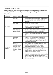
... LED ON · Using OSD, adjust brightness and contrast to maximum or reset to the monitor. shift, or too POSITION with non-standard signals. Abnormal Picture Display is ON. TROUBLESHOOTING Before sending your LCD monitor for a few seconds after adjusting the size of the image before changing or... disconnecting the signal cable or powering OFF the monitor. LED OFF · Check the power switch. small or too large in display · Using OSD, ...
... LED ON · Using OSD, adjust brightness and contrast to maximum or reset to the monitor. shift, or too POSITION with non-standard signals. Abnormal Picture Display is ON. TROUBLESHOOTING Before sending your LCD monitor for a few seconds after adjusting the size of the image before changing or... disconnecting the signal cable or powering OFF the monitor. LED OFF · Check the power switch. small or too large in display · Using OSD, ...
User Manual
Page 23
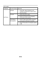
EN-22 (DVI mode) Problems No Picture Current Status Remedy LED ON · Using OSD, adjust brightness and contrast to maximum or reset to the monitor. LED displays blinking blue · Check if video signal cable is properly connected at the back of monitor. · Check if the power of computer system is properly connected to their default settings. LED OFF · Check the power switch. · Check if AC power cord is ON.
EN-22 (DVI mode) Problems No Picture Current Status Remedy LED ON · Using OSD, adjust brightness and contrast to maximum or reset to the monitor. LED displays blinking blue · Check if video signal cable is properly connected at the back of monitor. · Check if the power of computer system is properly connected to their default settings. LED OFF · Check the power switch. · Check if AC power cord is ON.


