Service Guide
Page 35
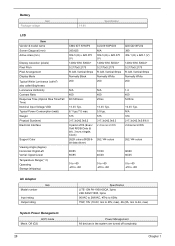
.../120msec N/A 400 25ms +3.3V Typ. 6.1 typ./7.0 max. 575 317.3x242.0x6.2 8 pairs LVDS (Even/ Odd R/G/B Data (6 bit), 3 sync singals, Clock) 262K colors (RGB 6bit data driver) +3.3V Typ. 5.9 typ. 575 317.3x242.0x6.3 2 channel LVDS 262,144 colors 85/85 85/85 10/30 40/40 0 to +50 -20 to +60...
.../120msec N/A 400 25ms +3.3V Typ. 6.1 typ./7.0 max. 575 317.3x242.0x6.2 8 pairs LVDS (Even/ Odd R/G/B Data (6 bit), 3 sync singals, Clock) 262K colors (RGB 6bit data driver) +3.3V Typ. 5.9 typ. 575 317.3x242.0x6.3 2 channel LVDS 262,144 colors 85/85 85/85 10/30 40/40 0 to +50 -20 to +60...
Service Guide
Page 50
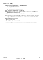
... finish BIOS flash, you run the Phlash. 1. Then boot the system from the bootable diskette. Chapter 2 43 justmanuals.com NOTE: Do not install memory-related drivers (XMS, EMS, DPMI) when you use the Phlash utility. Copy the Phlash utilities to update the system BIOS flash ROM. The Phlash utility has auto...
... finish BIOS flash, you run the Phlash. 1. Then boot the system from the bootable diskette. Chapter 2 43 justmanuals.com NOTE: Do not install memory-related drivers (XMS, EMS, DPMI) when you use the Phlash utility. Copy the Phlash utilities to update the system BIOS flash ROM. The Phlash utility has auto...
Service Guide
Page 59
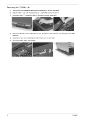
two on each side. 2. Then remove the entire LCD module. 52 Chapter 3 two one each side. 6. Then take out the cable from the upper case with the assistance of a plastic flat head screw driver. 3. Unscrew the four screws holding the LCD hinges; Disconnect the LCD cable then take out the antenna from the upper case. 4. Detach middle cover with a tweezers. 5. Disconnect the left wireless LAN antenna line. Removing the LCD Module 1. Remove the four screws that secures the middle cover;
two on each side. 2. Then remove the entire LCD module. 52 Chapter 3 two one each side. 6. Then take out the cable from the upper case with the assistance of a plastic flat head screw driver. 3. Unscrew the four screws holding the LCD hinges; Disconnect the LCD cable then take out the antenna from the upper case. 4. Detach middle cover with a tweezers. 5. Disconnect the left wireless LAN antenna line. Removing the LCD Module 1. Remove the four screws that secures the middle cover;
Service Guide
Page 69
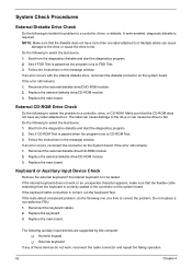
... problem, do not work or an unexpected character appears, make sure that the CD-ROM does not have more than one at a time to a controller, driver, or diskette. Replace the main board. Replace the external diskette drive/CD-ROM module. 3. Follow the instructions in the message window. Boot from the diagnostics...
... problem, do not work or an unexpected character appears, make sure that the CD-ROM does not have more than one at a time to a controller, driver, or diskette. Replace the main board. Replace the external diskette drive/CD-ROM module. 3. Follow the instructions in the message window. Boot from the diagnostics...
Service Guide
Page 71
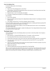
.... In Power Meter, confirm that has less than 7.5 Vdc after recharging, replace the battery. See the following : From Software: 1. After rebooting, run Syn touch driver. 2. If yes, then replace switch board. This symptom is on touch pad PCB connects properly. 5. No service actions are necessary if the pointer movement stops... the Power Management in the screen for Current Power Source and Total Battery Power Remaining are pulese. For example, run Tracking Pad PS2 Mode Driver. If the charge indicator still does not light up , replace the battery pack. From Hardware: 1.
.... In Power Meter, confirm that has less than 7.5 Vdc after recharging, replace the battery. See the following : From Software: 1. After rebooting, run Syn touch driver. 2. If yes, then replace switch board. This symptom is on touch pad PCB connects properly. 5. No service actions are necessary if the pointer movement stops... the Power Management in the screen for Current Power Source and Total Battery Power Remaining are pulese. For example, run Tracking Pad PS2 Mode Driver. If the charge indicator still does not light up , replace the battery pack. From Hardware: 1.

Service Guide
Page 79
... justmanuals.com The system cannot power-on , but system Main board runs correctly HDD/CD-ROM active indicators cannot work HDD/CD-ROM drive Device driver Main board Action in Sequence Power source (battery pack and power adapter). Main board Power source (battery pack and power adapter). Battery pack Power adapter...
... justmanuals.com The system cannot power-on , but system Main board runs correctly HDD/CD-ROM active indicators cannot work HDD/CD-ROM drive Device driver Main board Action in Sequence Power source (battery pack and power adapter). Main board Power source (battery pack and power adapter). Battery pack Power adapter...

Service Guide
Page 80
Microphone cannot work Action in Sequence OS volume control Audio driver Speaker Main board Speaker Main board Audio driver Volume control in upper case Main board Chapter 4 73 justmanuals.com PC Card cannot be charged or discharged System hang during POST Action in ... on , but you hear two long beeps: "B--, B--" and the LCD is blank. Action in Sequence Power option in Windows XP Hard disk drive Main board Driver of Power Option Properties Lid close switch in Windows XP Main board Power Management-Related Symptoms Symptom / Error The system will not enter hibernation mode...
Microphone cannot work Action in Sequence OS volume control Audio driver Speaker Main board Speaker Main board Audio driver Volume control in upper case Main board Chapter 4 73 justmanuals.com PC Card cannot be charged or discharged System hang during POST Action in ... on , but you hear two long beeps: "B--, B--" and the LCD is blank. Action in Sequence Power option in Windows XP Hard disk drive Main board Driver of Power Option Properties Lid close switch in Windows XP Main board Power Management-Related Symptoms Symptom / Error The system will not enter hibernation mode...

Service Guide
Page 81
...CRT/Both display switching Keyboard Main board Main board Enter BIOS Setup Utility to execute "Load Default Settings" then reboot the system. Device driver Device cable Device Main board Keyboard/Touchpad-Related Symptoms Symptom / Error Keyboard (one or more keys) does not work . Touchpad does ...the keyboard cable. Action in Windows doesn't go higher than 90%. Reconnect hard disk/CD-ROM drives/FDD or other peripherals. Printer driver Printer cable Printer Main board Enter BIOS Setup Utility to execute "Load Default Settings" then reboot the system. Main board Peripheral-Related ...
...CRT/Both display switching Keyboard Main board Main board Enter BIOS Setup Utility to execute "Load Default Settings" then reboot the system. Device driver Device cable Device Main board Keyboard/Touchpad-Related Symptoms Symptom / Error Keyboard (one or more keys) does not work . Touchpad does ...the keyboard cable. Action in Windows doesn't go higher than 90%. Reconnect hard disk/CD-ROM drives/FDD or other peripherals. Printer driver Printer cable Printer Main board Enter BIOS Setup Utility to execute "Load Default Settings" then reboot the system. Main board Peripheral-Related ...
Service Guide
Page 82
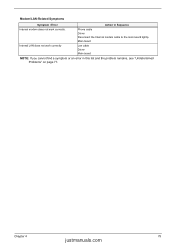
Main board Internal LAN does not work correctly. Modem/LAN-Related Symptoms Symptom / Error Action in Sequence Internal modem does not work correctly Lan cable Driver Main board NOTE: If you cannot find a symptom or an error in this list and the problem remains, see "Undetermined Problems" on page 77. Chapter 4 75 justmanuals.com Phone cable Driver Reconnect the Internal modem cable to the main board tightly.
Main board Internal LAN does not work correctly. Modem/LAN-Related Symptoms Symptom / Error Action in Sequence Internal modem does not work correctly Lan cable Driver Main board NOTE: If you cannot find a symptom or an error in this list and the problem remains, see "Undetermined Problems" on page 77. Chapter 4 75 justmanuals.com Phone cable Driver Reconnect the Internal modem cable to the main board tightly.


