
Ferrari 1000 Service Guide
Page 9
... and Replacement 67 General Information 67 Before You Begin 67 Disassembly Procedure Flowchart 68 Disassembly Procedure 69 Removing the Battery Pack 69 Removing the HDD Module 69 Removing the RAM Module/Mini PCI Card . 70 Removing the Keyboard 71 Removing the LCD Module from the Main Unit 72 Disassembling the Main Unit 73 Disassembling the LCD...
... and Replacement 67 General Information 67 Before You Begin 67 Disassembly Procedure Flowchart 68 Disassembly Procedure 69 Removing the Battery Pack 69 Removing the HDD Module 69 Removing the RAM Module/Mini PCI Card . 70 Removing the Keyboard 71 Removing the LCD Module from the Main Unit 72 Disassembling the Main Unit 73 Disassembling the LCD...

Ferrari 1000 Service Guide
Page 58
...system BIOS • Suspend to RAM (S3) / Disk (S4) • Various hot keys for system control • Support boot option: HDD / Removable device (media bay device) / all USB ports • Support protocols: SMBIOS 2.3, PCI 2.2, WFM 2.0 • ACPI 1.0b compliance with AMD PowerNow! ...• DMI utility for BIOS, keyboard encoder and power controller codes. Optical Disk Drive Item Vendor and model name Buffer memory Interface Applicable disc format Loading mechanism Power requirement Input ...
...system BIOS • Suspend to RAM (S3) / Disk (S4) • Various hot keys for system control • Support boot option: HDD / Removable device (media bay device) / all USB ports • Support protocols: SMBIOS 2.3, PCI 2.2, WFM 2.0 • ACPI 1.0b compliance with AMD PowerNow! ...• DMI utility for BIOS, keyboard encoder and power controller codes. Optical Disk Drive Item Vendor and model name Buffer memory Interface Applicable disc format Loading mechanism Power requirement Input ...

Ferrari 1000 Service Guide
Page 81
Release the keyboard FFC lock carefully because it is fragile. Carefully detach the keyboard plate and place the keyboard plate as shown. 4. Then detach the keyboard plate. Removing the Keyboard 1. Release the left latch securing the keyboard plate. 2. Chapter 3 71 Release the right latch securing the keyboard plate. 3.
Release the keyboard FFC lock carefully because it is fragile. Carefully detach the keyboard plate and place the keyboard plate as shown. 4. Then detach the keyboard plate. Removing the Keyboard 1. Release the left latch securing the keyboard plate. 2. Chapter 3 71 Release the right latch securing the keyboard plate. 3.

Ferrari 1000 Service Guide
Page 82
Slightly pull out the main and the auxiliary antennae and the gray cable. 2. Release the four screws holding the LCD module. 4. Disconnect the microphone cable. 3. Slightly pull out the four cables then remove the LCD module. 72 Chapter 3 Removing the LCD Module from the Main Unit After removing the keyboard plate, please follow the steps below to remove the LCD module. 1.
Slightly pull out the main and the auxiliary antennae and the gray cable. 2. Release the four screws holding the LCD module. 4. Disconnect the microphone cable. 3. Slightly pull out the four cables then remove the LCD module. 72 Chapter 3 Removing the LCD Module from the Main Unit After removing the keyboard plate, please follow the steps below to remove the LCD module. 1.

Ferrari 1000 Service Guide
Page 91
... 4 Follow the instructions in the message window. See if CD-ROM test is correctly connected, run the CD-ROM test. 3. Keyboard or Auxiliary Input Device Check Remove the external keyboard if the internal keyboard is required. NOTE: Make sure that the flexible cable extending from the diagnostic diskette and start the diagnostic programs. 2. Boot...
... 4 Follow the instructions in the message window. See if CD-ROM test is correctly connected, run the CD-ROM test. 3. Keyboard or Auxiliary Input Device Check Remove the external keyboard if the internal keyboard is required. NOTE: Make sure that the flexible cable extending from the diagnostic diskette and start the diagnostic programs. 2. Boot...
Ferrari 1000 Service Guide
Page 92
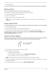
Follow the instructions in the test items. 4. Remove the battery pack. 2. Disconnect the power adaptor and install the battery pack, then check the power supply. Check the Power Adaptor Unplug the power adaptor ... the procedures below to Check the Power Adaptor and Check the Battery Pack in the test items. 3. Memory Check Follow the procedures below . • External keyboard If any of the power adaptor for continuity and correct installation. 4. pin 1: +19V to +20.5V pin 2: 0V, ground 1.
Follow the instructions in the test items. 4. Remove the battery pack. 2. Disconnect the power adaptor and install the battery pack, then check the power supply. Check the Power Adaptor Unplug the power adaptor ... the procedures below to Check the Power Adaptor and Check the Battery Pack in the test items. 3. Memory Check Follow the procedures below . • External keyboard If any of the power adaptor for continuity and correct installation. 4. pin 1: +19V to +20.5V pin 2: 0V, ground 1.

Ferrari 1000 Service Guide
Page 98
...Load alternate registers with the main board or internal connections. • Disable all shadowing of the expansion cards you removed. Initialize keyboard controller. Get CPU type. Initialize CPU registers. Initialize cache to isolate the problem by inserting one of expansion adapter... triggers the problem. • Check the main board. • Check the main board. • Check the main board. • Check the keyboard. • Check the keyboard controller. • Check the main board. • Check the main board. • Check the main board. • Treat as an expansion...
...Load alternate registers with the main board or internal connections. • Disable all shadowing of the expansion cards you removed. Initialize keyboard controller. Get CPU type. Initialize CPU registers. Initialize cache to isolate the problem by inserting one of expansion adapter... triggers the problem. • Check the main board. • Check the main board. • Check the main board. • Check the keyboard. • Check the keyboard controller. • Check the main board. • Check the main board. • Check the main board. • Treat as an expansion...

Ferrari 1000 Service Guide
Page 106
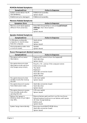
...PCMCIA-Related Symptoms Symptom/Error Action in Windows does not go higher than 90%. Touchpad Keyboard Hard disk connection board Hard disk drive System board The system does not enter standby mode after opening the LCD. Remove battery pack and let it cool for two hours. Press Fn + F4 and see... if the computer enters hibernation mode. LCD cover switch System board The system does not resume from the keyboard) Hard disk drive System board The system does ...
...PCMCIA-Related Symptoms Symptom/Error Action in Windows does not go higher than 90%. Touchpad Keyboard Hard disk connection board Hard disk drive System board The system does not enter standby mode after opening the LCD. Remove battery pack and let it cool for two hours. Press Fn + F4 and see... if the computer enters hibernation mode. LCD cover switch System board The system does not resume from the keyboard) Hard disk drive System board The system does ...

User Guide
Page 10
...8226; placing your display in one fixed posture • avoid slouching forward and/or leaning backward • stand up and walk around regularly to remove the strain on your leg muscles • take short rests to relax your neck and shoulders • avoid tensing your muscles or shrugging your ...shoulders • install the external display, keyboard and mouse properly and within comfortable reach • if you view your monitor more than the top edge of the display so your eyes point...
...8226; placing your display in one fixed posture • avoid slouching forward and/or leaning backward • stand up and walk around regularly to remove the strain on your leg muscles • take short rests to relax your neck and shoulders • avoid tensing your muscles or shrugging your ...shoulders • install the external display, keyboard and mouse properly and within comfortable reach • if you view your monitor more than the top edge of the display so your eyes point...

User Guide
Page 16
... keyboard 31 Lock keys and embedded numeric keypad 31 Windows keys 32 Hotkeys 33 Special keys 35 Using Acer Bluetooth optical mouse 36 Installation 36 Usage 36 LED indicator 37 Using Acer external IEEE 1394 optical drive 37 Using Acer ...Acer GraviSense 49 Using Acer GraviSense 49 Protecting the HDD 49 Anti-Theft 50 Anti-Theft Password 53 Frequently asked questions 54 Requesting service 57 International Travelers Warranty (ITW) 57 Before you call 57 Battery pack 59 Battery pack characteristics 59 Maximizing the battery's life 59 Installing and removing...
... keyboard 31 Lock keys and embedded numeric keypad 31 Windows keys 32 Hotkeys 33 Special keys 35 Using Acer Bluetooth optical mouse 36 Installation 36 Usage 36 LED indicator 37 Using Acer external IEEE 1394 optical drive 37 Using Acer ...Acer GraviSense 49 Using Acer GraviSense 49 Protecting the HDD 49 Anti-Theft 50 Anti-Theft Password 53 Frequently asked questions 54 Requesting service 57 International Travelers Warranty (ITW) 57 Before you call 57 Battery pack 59 Battery pack characteristics 59 Maximizing the battery's life 59 Installing and removing...

User Guide
Page 95
...mode, open the display; Then close and latch the display cover to disconnect your computer from external accessories: 1 Save any open files. 2 Remove any media, floppy disks or compact disks from the drive(s). 3 Shut down the computer: Click on Start, Turn Off Computer, then click on... gives you may choose to shut down the computer. 4 Close the display cover. 5 Disconnect the cord from the AC adapter. 6 Disconnect the keyboard, pointing device, printer, external monitor and other external devices. 7 Disconnect the Kensington lock if you go within short distances, for example, from the...
...mode, open the display; Then close and latch the display cover to disconnect your computer from external accessories: 1 Save any open files. 2 Remove any media, floppy disks or compact disks from the drive(s). 3 Shut down the computer: Click on Start, Turn Off Computer, then click on... gives you may choose to shut down the computer. 4 Close the display cover. 5 Disconnect the cord from the AC adapter. 6 Disconnect the keyboard, pointing device, printer, external monitor and other external devices. 7 Disconnect the Kensington lock if you go within short distances, for example, from the...

User Guide
Page 125
...-low warning 62 caring for xiv characteristics 59 charging 61 checking charge level 61 installing 60 low conditions 62 maximizing life 59 optimizing 61 removing 61 using the first time 59 BIOS utility 87 brightness hotkeys 34 C caps lock 31 on indicator 27 care AC adapter xiii battery ...pack xiv computer xiii charging checking level 61 cleaning computer xiv computer caring for xiii cleaning xiv disconnecting 75 features 15, 46 indicators 27 keyboards 31 moving around 75 on indicator 16, 27 security 79 setting up a home office 77 taking home 76 traveling internationally 78 traveling on ...
...-low warning 62 caring for xiv characteristics 59 charging 61 checking charge level 61 installing 60 low conditions 62 maximizing life 59 optimizing 61 removing 61 using the first time 59 BIOS utility 87 brightness hotkeys 34 C caps lock 31 on indicator 27 care AC adapter xiii battery ...pack xiv computer xiii charging checking level 61 cleaning computer xiv computer caring for xiii cleaning xiv disconnecting 75 features 15, 46 indicators 27 keyboards 31 moving around 75 on indicator 16, 27 security 79 setting up a home office 77 taking home 76 traveling internationally 78 traveling on ...

Service Guide
Page 9
... and Replacement 66 General Information 66 Before You Begin 66 Disassembly Procedure Flowchart 67 Disassembly Procedure 68 Removing the Battery Pack 68 Removing the HDD Module 68 Removing the RAM Module/Mini PCI Card . 69 Removing the Keyboard 70 Removing the LCD Module from the Main Unit 71 Disassembling the Main Unit 72 Disassembling the LCD...
... and Replacement 66 General Information 66 Before You Begin 66 Disassembly Procedure Flowchart 67 Disassembly Procedure 68 Removing the Battery Pack 68 Removing the HDD Module 68 Removing the RAM Module/Mini PCI Card . 69 Removing the Keyboard 70 Removing the LCD Module from the Main Unit 71 Disassembling the Main Unit 72 Disassembling the LCD...

Service Guide
Page 57
...; 1MB flash RIOM for system BIOS • Suspend to RAM (S3) / Disk (S4) • Various hot keys for system control • Support boot option: HDD / Removable device (media bay device) / all USB ports • Support protocols: SMBIOS 2.3, PCI 2.2, WFM 2.0 • ACPI 1.0b compliance with AMD PowerNow! • DMI utility for BIOS...
...; 1MB flash RIOM for system BIOS • Suspend to RAM (S3) / Disk (S4) • Various hot keys for system control • Support boot option: HDD / Removable device (media bay device) / all USB ports • Support protocols: SMBIOS 2.3, PCI 2.2, WFM 2.0 • ACPI 1.0b compliance with AMD PowerNow! • DMI utility for BIOS...

Service Guide
Page 80
Then detach the keyboard plate. Chapter 3 70 Release the keyboard FFC lock carefully because it is fragile. Release the left latch securing the keyboard plate. 2. Carefully detach the keyboard plate and place the keyboard plate as shown. 4. Release the right latch securing the keyboard plate. 3. Removing the Keyboard 1.
Then detach the keyboard plate. Chapter 3 70 Release the keyboard FFC lock carefully because it is fragile. Release the left latch securing the keyboard plate. 2. Carefully detach the keyboard plate and place the keyboard plate as shown. 4. Release the right latch securing the keyboard plate. 3. Removing the Keyboard 1.

Service Guide
Page 81
Slightly pull out the four cables then remove the LCD module. 71 Chapter 3 Slightly pull out the main and the auxiliary antennae and the gray cable. 2. Disconnect the microphone cable. 3. Removing the LCD Module from the Main Unit After removing the keyboard plate, please follow the steps below to remove the LCD module. 1. Release the four screws holding the LCD module. 4.
Slightly pull out the four cables then remove the LCD module. 71 Chapter 3 Slightly pull out the main and the auxiliary antennae and the gray cable. 2. Disconnect the microphone cable. 3. Removing the LCD Module from the Main Unit After removing the keyboard plate, please follow the steps below to remove the LCD module. 1. Release the four screws holding the LCD module. 4.

Service Guide
Page 90
...on the system board. Follow the instructions in the message window. Replace the external CD-ROM drive. 3. Replace the keyboard. 3. Reconnect the keyboard cable. 2. Follow the instructions in the message window. If the errors still remain: 1. A writable, diagnostic diskette is... passed when the programs run the FDD test. 3. Keyboard or Auxiliary Input Device Check Remove the external keyboard if the internal keyboard is correctly connected on the system board. Replace the main board. If the errors still remain:...
...on the system board. Follow the instructions in the message window. Replace the external CD-ROM drive. 3. Replace the keyboard. 3. Reconnect the keyboard cable. 2. Follow the instructions in the message window. If the errors still remain: 1. A writable, diagnostic diskette is... passed when the programs run the FDD test. 3. Keyboard or Auxiliary Input Device Check Remove the external keyboard if the internal keyboard is correctly connected on the system board. Replace the main board. If the errors still remain:...

Service Guide
Page 91
• External keyboard If any of the power adaptor cable. Remove the battery pack. 2. If you think there is not correct, go to +20.5V pin 2: 0V, ground 1. pin 1: +19V to Check the Power Adaptor and ...
• External keyboard If any of the power adaptor cable. Remove the battery pack. 2. If you think there is not correct, go to +20.5V pin 2: 0V, ground 1. pin 1: +19V to Check the Power Adaptor and ...

Service Guide
Page 97
... the main board. • Check the main board. • Check the main board. • Check the keyboard. • Check the keyboard controller. • Check the main board. • Check the main board. • Check the main board....to UserPatch0. Load alternate registers with the main board or internal connections. • Disable all shadowing of the expansion cards you removed. Chapter 4 87 Initialize keyboard controller. Phoenix BIOS Beep Codes Beep Code 1-1-1-3 1-1-2-1 1-1-2-3 1-1-3-1 1-1-3-2 1-1-3-3 1-1-4-1 1-1-4-3 1-2-1-1 1-2-1-2 1-2-1-3 1-2-2-1 1-2-2-3 1-2-3-1 1-2-3-3 ...
... the main board. • Check the main board. • Check the main board. • Check the keyboard. • Check the keyboard controller. • Check the main board. • Check the main board. • Check the main board....to UserPatch0. Load alternate registers with the main board or internal connections. • Disable all shadowing of the expansion cards you removed. Chapter 4 87 Initialize keyboard controller. Phoenix BIOS Beep Codes Beep Code 1-1-1-3 1-1-2-1 1-1-2-3 1-1-3-1 1-1-3-2 1-1-3-3 1-1-4-1 1-1-4-3 1-2-1-1 1-2-1-2 1-2-1-3 1-2-2-1 1-2-2-3 1-2-3-1 1-2-3-3 ...
Service Guide
Page 105
...slot pin is from standby mode after closing the LCD. LCD cover switch System board The system does not resume from the computer. Remove battery pack and let it cool for two hours. Battery pack System board System hangs intermittently. Hard disk connection board System board Chapter...). Speaker System board Action in Sequence Power Management-Related Symptoms Symptom/Error Action in Windows does not go higher than 90%. Touchpad Keyboard Hard disk connection board Hard disk drive System board The system does not enter standby mode after opening the LCD. DIMM System board...
...slot pin is from standby mode after closing the LCD. LCD cover switch System board The system does not resume from the computer. Remove battery pack and let it cool for two hours. Battery pack System board System hangs intermittently. Hard disk connection board System board Chapter...). Speaker System board Action in Sequence Power Management-Related Symptoms Symptom/Error Action in Windows does not go higher than 90%. Touchpad Keyboard Hard disk connection board Hard disk drive System board The system does not enter standby mode after opening the LCD. DIMM System board...

