
Ferrari 1000 Service Guide
Page 9
...61 Exit 62 BIOS Password Removal SOP 63 HDD Password Removal SOP 65 Chapter Three Machine Disassembly and Replacement 67 General Information 67 Before You Begin 67 Disassembly Procedure Flowchart 68 Disassembly Procedure 69 Removing the Battery Pack 69 Removing the HDD Module 69 Removing the RAM ...Module/Mini PCI Card . 70 Removing the Keyboard 71 Removing the LCD Module from the Main Unit 72 Disassembling the Main Unit 73 Disassembling the LCD Module 77 Chapter Four Troubleshooting 80 System Check Procedures 81 External Diskette Drive Check 81 External CD-ROM Drive...
...61 Exit 62 BIOS Password Removal SOP 63 HDD Password Removal SOP 65 Chapter Three Machine Disassembly and Replacement 67 General Information 67 Before You Begin 67 Disassembly Procedure Flowchart 68 Disassembly Procedure 69 Removing the Battery Pack 69 Removing the HDD Module 69 Removing the RAM ...Module/Mini PCI Card . 70 Removing the Keyboard 71 Removing the LCD Module from the Main Unit 72 Disassembling the Main Unit 73 Disassembling the LCD Module 77 Chapter Four Troubleshooting 80 System Check Procedures 81 External Diskette Drive Check 81 External CD-ROM Drive...
Ferrari 1000 Service Guide
Page 77
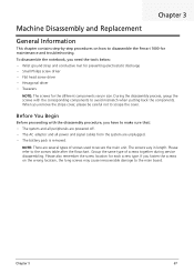
... main unit. If you remove the stripe cover, please be careful not to scrape the cover. When you fasten the screws on how to disassemble the Ferrari 1000 for maintenance and troubleshooting. Before You Begin Before proceeding with the corresponding components to avoid mismatch when putting back the components. Please also remember the...
... main unit. If you remove the stripe cover, please be careful not to scrape the cover. When you fasten the screws on how to disassemble the Ferrari 1000 for maintenance and troubleshooting. Before You Begin Before proceeding with the corresponding components to avoid mismatch when putting back the components. Please also remember the...

Ferrari 1000 Service Guide
Page 78
Disassembly Procedure Flowchart The flowchart gives you a graphic representation on the entire disassembly and reassembly and instructs you how to remove the components. # Description a SCREW M2*5-I(BZN)(NYLOK) b SCREW M1.6*4.0-I (NI)(NYLOK) c SCREW M2.0*3.0-I(BZN)(NYLOK) d SCREW M2*2.5-I(NI)(NYLOK) e SCREW M2.5*6-I(BNI)(NYLOK) f SCREW M3*0.5+3.5I g SCREW M2.5*4.0-I(NYLOK)EU h I2.5*4T-BKAGH(4,0.8) i SCREW M2.5*4-I(BNI) Acer Part No. 86.FR6V7.001 86.FR6V7.002 86.FR6V7.003 86.FR6V7.004 86.A08V7.004 86.A03V7.011 86.A03V7.009 86.FR6V7.005 86.T23V7.009 68 Chapter 3
Disassembly Procedure Flowchart The flowchart gives you a graphic representation on the entire disassembly and reassembly and instructs you how to remove the components. # Description a SCREW M2*5-I(BZN)(NYLOK) b SCREW M1.6*4.0-I (NI)(NYLOK) c SCREW M2.0*3.0-I(BZN)(NYLOK) d SCREW M2*2.5-I(NI)(NYLOK) e SCREW M2.5*6-I(BNI)(NYLOK) f SCREW M3*0.5+3.5I g SCREW M2.5*4.0-I(NYLOK)EU h I2.5*4T-BKAGH(4,0.8) i SCREW M2.5*4-I(BNI) Acer Part No. 86.FR6V7.001 86.FR6V7.002 86.FR6V7.003 86.FR6V7.004 86.A08V7.004 86.A03V7.011 86.A03V7.009 86.FR6V7.005 86.T23V7.009 68 Chapter 3
Ferrari 1000 Service Guide
Page 79
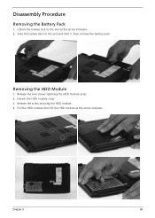
Chapter 3 69 Then remove the battery pack. Removing the HDD Module 1. Slide the battery latch to the end as the arrow indicates. Detach the HDD module cover. 3. Release the screw securing the HDD module. 4. Pull the HDD module then lift the HDD module as the arrow indicates. 2. Release the two screws fastening the HDD module cover. 2. Disassembly Procedure Removing the Battery Pack 1. Unlock the battery lock to the end and hold it.
Chapter 3 69 Then remove the battery pack. Removing the HDD Module 1. Slide the battery latch to the end as the arrow indicates. Detach the HDD module cover. 3. Release the screw securing the HDD module. 4. Pull the HDD module then lift the HDD module as the arrow indicates. 2. Release the two screws fastening the HDD module cover. 2. Disassembly Procedure Removing the Battery Pack 1. Unlock the battery lock to the end and hold it.

Ferrari 1000 Service Guide
Page 83
... then disconnect the power button board FFC. 4. Chapter 3 73 Release the 18 screws securing the upper case and the lower case on the upper side. 5. Disassembling the Main Unit Separating the Upper Case and the Lower Case 1. Slightly release the click button board FFC lock then disconnect the click button board...
... then disconnect the power button board FFC. 4. Chapter 3 73 Release the 18 screws securing the upper case and the lower case on the upper side. 5. Disassembling the Main Unit Separating the Upper Case and the Lower Case 1. Slightly release the click button board FFC lock then disconnect the click button board...

Ferrari 1000 Service Guide
Page 87
Detach the mylars covered on screws then release the six screws securing the LCD bezel. 2. Chapter 3 77 Carefully disconnect the LVDS cable. 2. Disassembling the LCD Module Removing the LCD Bezel 1. Removing the Inverter Board 1. Carefully detach the LCD bezel from the LCD module as shown till the LCD bezel is total removed. Carefully disconnect the LCD cable then remove the inverter board.
Detach the mylars covered on screws then release the six screws securing the LCD bezel. 2. Chapter 3 77 Carefully disconnect the LVDS cable. 2. Disassembling the LCD Module Removing the LCD Bezel 1. Removing the Inverter Board 1. Carefully detach the LCD bezel from the LCD module as shown till the LCD bezel is total removed. Carefully disconnect the LCD cable then remove the inverter board.

User Guide
Page 5
... result in fire. Use of other risks. Product servicing Do not attempt to replace the power cord set . Unplug this product from children. Do not disassemble or dispose of used batteries.
... result in fire. Use of other risks. Product servicing Do not attempt to replace the power cord set . Unplug this product from children. Do not disassemble or dispose of used batteries.

User Guide
Page 117
... authorized by U.S. LAVATTAESSA OLET ALTTINA LASERSÅTEILYLLE. and 6,516,132." This product incorporates copyright protection technology that is protected by Macrovision. Reverse engineering or disassembly is intended for home and other intellectual property rights. Macrovision copyright protection notice "U.S Patent Nos. 4,631,603; 4,819,098; 4,907,093; 5,315,448; Nevertheless, some...
... authorized by U.S. LAVATTAESSA OLET ALTTINA LASERSÅTEILYLLE. and 6,516,132." This product incorporates copyright protection technology that is protected by Macrovision. Reverse engineering or disassembly is intended for home and other intellectual property rights. Macrovision copyright protection notice "U.S Patent Nos. 4,631,603; 4,819,098; 4,907,093; 5,315,448; Nevertheless, some...

Service Guide
Page 9
...60 Exit 61 BIOS Password Removal SOP 62 HDD Password Removal SOP 64 Chapter Three Machine Disassembly and Replacement 66 General Information 66 Before You Begin 66 Disassembly Procedure Flowchart 67 Disassembly Procedure 68 Removing the Battery Pack 68 Removing the HDD Module 68 Removing the RAM ...Module/Mini PCI Card . 69 Removing the Keyboard 70 Removing the LCD Module from the Main Unit 71 Disassembling the Main Unit 72 Disassembling the LCD Module 76 Chapter Four Troubleshooting 79 System Check Procedures 80 External Diskette Drive Check 80 External CD-ROM Drive...
...60 Exit 61 BIOS Password Removal SOP 62 HDD Password Removal SOP 64 Chapter Three Machine Disassembly and Replacement 66 General Information 66 Before You Begin 66 Disassembly Procedure Flowchart 67 Disassembly Procedure 68 Removing the Battery Pack 68 Removing the HDD Module 68 Removing the RAM ...Module/Mini PCI Card . 69 Removing the Keyboard 70 Removing the LCD Module from the Main Unit 71 Disassembling the Main Unit 72 Disassembling the LCD Module 76 Chapter Four Troubleshooting 79 System Check Procedures 80 External Diskette Drive Check 80 External CD-ROM Drive...

Service Guide
Page 76
..., you remove the stripe cover, please be careful not to the screws table after the flowchart. Chapter 3 Machine Disassembly and Replacement General Information This chapter contains step-by-step procedures on the wrong location, the long screws may cause ... adaptor and all power and signal cables from the system are several types of screws together during service disassembling. Before You Begin Before proceeding with the corresponding components to disassemble the Ferrari 1000 for each screw type. Please refer to scrape the cover. When you need the tools below: &#...
..., you remove the stripe cover, please be careful not to the screws table after the flowchart. Chapter 3 Machine Disassembly and Replacement General Information This chapter contains step-by-step procedures on the wrong location, the long screws may cause ... adaptor and all power and signal cables from the system are several types of screws together during service disassembling. Before You Begin Before proceeding with the corresponding components to disassemble the Ferrari 1000 for each screw type. Please refer to scrape the cover. When you need the tools below: &#...

Service Guide
Page 77
Disassembly Procedure Flowchart The flowchart gives you a graphic representation on the entire disassembly and reassembly and instructs you how to remove the components. # Description a SCREW M2*5-I(BZN)(NYLOK) b SCREW M1.6*4.0-I (NI)(NYLOK) c SCREW M2.0*3.0-I(BZN)(NYLOK) d SCREW M2*2.5-I(NI)(NYLOK) e SCREW M2.5*6-I(BNI)(NYLOK) f SCREW M3*0.5+3.5I g SCREW M2.5*4.0-I(NYLOK)EU h I2.5*4T-BKAGH(4,0.8) i SCREW M2.5*4-I(BNI) Acer Part No. 86.FR6V7.001 86.FR6V7.002 86.FR6V7.003 86.FR6V7.004 86.A08V7.004 86.A03V7.011 86.A03V7.009 86.FR6V7.005 86.T23V7.009 67 Chapter 3
Disassembly Procedure Flowchart The flowchart gives you a graphic representation on the entire disassembly and reassembly and instructs you how to remove the components. # Description a SCREW M2*5-I(BZN)(NYLOK) b SCREW M1.6*4.0-I (NI)(NYLOK) c SCREW M2.0*3.0-I(BZN)(NYLOK) d SCREW M2*2.5-I(NI)(NYLOK) e SCREW M2.5*6-I(BNI)(NYLOK) f SCREW M3*0.5+3.5I g SCREW M2.5*4.0-I(NYLOK)EU h I2.5*4T-BKAGH(4,0.8) i SCREW M2.5*4-I(BNI) Acer Part No. 86.FR6V7.001 86.FR6V7.002 86.FR6V7.003 86.FR6V7.004 86.A08V7.004 86.A03V7.011 86.A03V7.009 86.FR6V7.005 86.T23V7.009 67 Chapter 3

Service Guide
Page 78
Removing the HDD Module 1. Pull the HDD module then lift the HDD module as the arrow indicates. 2. Chapter 3 68 Then remove the battery pack. Slide the battery latch to the end as the arrow indicates. Release the screw securing the HDD module. 4. Detach the HDD module cover. 3. Unlock the battery lock to the end and hold it. Release the two screws fastening the HDD module cover. 2. Disassembly Procedure Removing the Battery Pack 1.
Removing the HDD Module 1. Pull the HDD module then lift the HDD module as the arrow indicates. 2. Chapter 3 68 Then remove the battery pack. Slide the battery latch to the end as the arrow indicates. Release the screw securing the HDD module. 4. Detach the HDD module cover. 3. Unlock the battery lock to the end and hold it. Release the two screws fastening the HDD module cover. 2. Disassembly Procedure Removing the Battery Pack 1.

Service Guide
Page 82
... Release the 18 screws securing the upper case and the lower case on the upper side. 5. Then detach the upper case from the main unit. Disassembling the Main Unit Separating the Upper Case and the Lower Case 1. Slightly release the click button board FFC lock then disconnect the click button board...
... Release the 18 screws securing the upper case and the lower case on the upper side. 5. Then detach the upper case from the main unit. Disassembling the Main Unit Separating the Upper Case and the Lower Case 1. Slightly release the click button board FFC lock then disconnect the click button board...

Service Guide
Page 86
Carefully detach the LCD bezel from the LCD module as shown till the LCD bezel is total removed. Carefully disconnect the LVDS cable. 2. Carefully disconnect the LCD cable then remove the inverter board. Chapter 3 76 Disassembling the LCD Module Removing the LCD Bezel 1. Removing the Inverter Board 1. Detach the mylars covered on screws then release the six screws securing the LCD bezel. 2.
Carefully detach the LCD bezel from the LCD module as shown till the LCD bezel is total removed. Carefully disconnect the LVDS cable. 2. Carefully disconnect the LCD cable then remove the inverter board. Chapter 3 76 Disassembling the LCD Module Removing the LCD Bezel 1. Removing the Inverter Board 1. Detach the mylars covered on screws then release the six screws securing the LCD bezel. 2.


