TravelMate 5520G Service Guide
Page 8
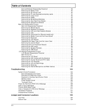
...Heatsink Fan Module 70 Removing the CPU and VGA Heatsink Module 71 Removing the CPU 73 Removing the VGA board (for Discrete model only 74 Removing the Middle Cover and the Power Board 75 Removing the Keyboard 77 Removing the LCD Module 79 Separating the Upper Case from the Lower Case ...82 Removing the Launch Board 85 Removing theTouch Pad Board Module 86 Removing the main board 89 Removing the Speaker Modules 91 Removing the ...
...Heatsink Fan Module 70 Removing the CPU and VGA Heatsink Module 71 Removing the CPU 73 Removing the VGA board (for Discrete model only 74 Removing the Middle Cover and the Power Board 75 Removing the Keyboard 77 Removing the LCD Module 79 Separating the Upper Case from the Lower Case ...82 Removing the Launch Board 85 Removing theTouch Pad Board Module 86 Removing the main board 89 Removing the Speaker Modules 91 Removing the ...
TravelMate 5520G Service Guide
Page 79
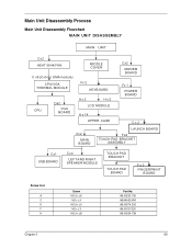
.../VGA THERMAL MODULE Fx 2 KEYBOARD CPU Dx2 VGA BOARD Ax2 Hx2 LCD MODULE A x 14 Cx2 MODEM BOARD Fx 1 POWER BOARD UPPER CASE Cx2 Cx2 MAIN BOARD LAUNCH BOARD Fx2 TOUCH PAD BRACKET ASSEMBLY Cx1 USB BOARD Cx4 LEFT AND RIGHT SPEAKER MODULE TOUCH PAD BRACKET TOUCH PAD BOARD Fx2 FINGERPRINT BOARD Screw List A C D F H Screw M2.5 x L6 M2 x L4 M2...
.../VGA THERMAL MODULE Fx 2 KEYBOARD CPU Dx2 VGA BOARD Ax2 Hx2 LCD MODULE A x 14 Cx2 MODEM BOARD Fx 1 POWER BOARD UPPER CASE Cx2 Cx2 MAIN BOARD LAUNCH BOARD Fx2 TOUCH PAD BRACKET ASSEMBLY Cx1 USB BOARD Cx4 LEFT AND RIGHT SPEAKER MODULE TOUCH PAD BRACKET TOUCH PAD BOARD Fx2 FINGERPRINT BOARD Screw List A C D F H Screw M2.5 x L6 M2 x L4 M2...
TravelMate 5520G Service Guide
Page 85
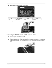
... the way to facilitate the easy removal of the middle cover and gently pry up the middle cover. Remove the two screws (D) securing the VGA board. Continue prying on page 60. 2. Carefully remove the VGA board from the main board. Torque 1.6 kgf-cm Removing the Middle Cover and the Power Board 1. 5. Chapter 3 75
... the way to facilitate the easy removal of the middle cover and gently pry up the middle cover. Remove the two screws (D) securing the VGA board. Continue prying on page 60. 2. Carefully remove the VGA board from the main board. Torque 1.6 kgf-cm Removing the Middle Cover and the Power Board 1. 5. Chapter 3 75

TravelMate 5520G Service Guide
Page 86
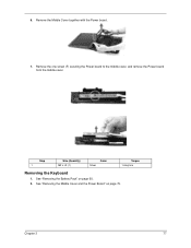
4. Disconnect the Power board cable from the main board and disconnect the Power board cable. 76 Chapter 3 Detach the cover and turn it over on the keyboard. 5.
4. Disconnect the Power board cable from the main board and disconnect the Power board cable. 76 Chapter 3 Detach the cover and turn it over on the keyboard. 5.
TravelMate 5520G Service Guide
Page 87
Remove the one screw (F) securing the Power board to the middle cover, and remove the Power board from the middle cover. See "Removing the Battery Pack" on page 75. 6. Remove the Middle Cover together with the Power board. 7. See "Removing the Middle Cover and the Power Board" on page 60.. 2. Step 1 Size (Quantity) M2 x L3 (1) Color Silver Torque 1.6 kgf-cm Removing the Keyboard 1. Chapter 3 77
Remove the one screw (F) securing the Power board to the middle cover, and remove the Power board from the middle cover. See "Removing the Battery Pack" on page 75. 6. Remove the Middle Cover together with the Power board. 7. See "Removing the Middle Cover and the Power Board" on page 60.. 2. Step 1 Size (Quantity) M2 x L3 (1) Color Silver Torque 1.6 kgf-cm Removing the Keyboard 1. Chapter 3 77

TravelMate 5520G Service Guide
Page 89
Removing the LCD Module 1. See "Removing the Middle Cover and the Power Board" on page 77. See "Removing the Keyboard" on page 75. 5. Chapter 3 79 Disconnect the keyboard cable from the main board to remove the keyboard. See "Removing the Lower Cover" on page 60. 2. See "Removing the Battery Pack" on page 62. 3. See "Removing the WLAN Board Modules" on page 64. 4. 5.
Removing the LCD Module 1. See "Removing the Middle Cover and the Power Board" on page 77. See "Removing the Keyboard" on page 75. 5. Chapter 3 79 Disconnect the keyboard cable from the main board to remove the keyboard. See "Removing the Lower Cover" on page 60. 2. See "Removing the Battery Pack" on page 62. 3. See "Removing the WLAN Board Modules" on page 64. 4. 5.
TravelMate 5520G Service Guide
Page 92
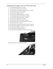
.... 2. See "Removing the Optical Drive Module" on page 65. 8. See "Removing the Hard Disk Drive Module" on page 66. 9. See "Removing the Modem Board" on page 74. 14. See "Removing the VGA board (for Discrete model only)" on page 70. 10. Disconnect the cover switch cable from the main... 75. 15. Separating the Upper Case from the Lower Case 1. See "Removing the Middle Cover and the Power Board" on page 79. 17. See "Removing the DIMM" on page 64. 7. See "Removing the WLAN Board Modules" on page 63. 6. See "Removing the CPU and VGA Heatsink Module" on page 73. 13....
.... 2. See "Removing the Optical Drive Module" on page 65. 8. See "Removing the Hard Disk Drive Module" on page 66. 9. See "Removing the Modem Board" on page 74. 14. See "Removing the VGA board (for Discrete model only)" on page 70. 10. Disconnect the cover switch cable from the main... 75. 15. Separating the Upper Case from the Lower Case 1. See "Removing the Middle Cover and the Power Board" on page 79. 17. See "Removing the DIMM" on page 64. 7. See "Removing the WLAN Board Modules" on page 63. 6. See "Removing the CPU and VGA Heatsink Module" on page 73. 13....
TravelMate 5520G Service Guide
Page 95
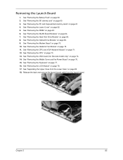
... CPU and VGA Heatsink Module" on page 60. 2. See "Removing the Middle Cover and the Power Board" on page 79. 17. See "Removing the LCD Module" on page 75. 15. See "Separating the Upper Case from the launch board. Chapter 3 85 See "Removing the Lower Cover" on page 63. 6. See "Removing the DIMM..." on page 73. 13. See "Removing the CPU" on page 70. 11. See "Removing the SD dummy card" on page 64. 7. See "Removing the WLAN Board Modules" on page 60. 3. See "Removing the PC and ExpressCard dummy cards" on page 77. 16. See "Removing the Keyboard" on page 61. 4. Release the...
... CPU and VGA Heatsink Module" on page 60. 2. See "Removing the Middle Cover and the Power Board" on page 79. 17. See "Removing the LCD Module" on page 75. 15. See "Separating the Upper Case from the launch board. Chapter 3 85 See "Removing the Lower Cover" on page 63. 6. See "Removing the DIMM..." on page 73. 13. See "Removing the CPU" on page 70. 11. See "Removing the SD dummy card" on page 64. 7. See "Removing the WLAN Board Modules" on page 60. 3. See "Removing the PC and ExpressCard dummy cards" on page 77. 16. See "Removing the Keyboard" on page 61. 4. Release the...
TravelMate 5520G Service Guide
Page 96
... page 62. 5. See "Removing the Lower Cover" on page 77. 16. See "Removing the SD dummy card" on page 70. 10. See "Removing the Modem Board" on page 60. 3. See "Removing the LCD Module" on page 64. 7. See "Separating the Upper Case from the upper cover. See "Removing the WLAN... Heatsink Fan Module" on page 65. 8. See "Removing the CPU and VGA Heatsink Module" on page 75. 15. Remove the one screw (F) holding the launch board and remove the launch board from the Lower Case" on page 82. 86 Chapter 3 See "Removing the Middle Cover and the Power Board" on page 71. 12.
... page 62. 5. See "Removing the Lower Cover" on page 77. 16. See "Removing the SD dummy card" on page 70. 10. See "Removing the Modem Board" on page 60. 3. See "Removing the LCD Module" on page 64. 7. See "Separating the Upper Case from the upper cover. See "Removing the WLAN... Heatsink Fan Module" on page 65. 8. See "Removing the CPU and VGA Heatsink Module" on page 75. 15. Remove the one screw (F) holding the launch board and remove the launch board from the Lower Case" on page 82. 86 Chapter 3 See "Removing the Middle Cover and the Power Board" on page 71. 12.
TravelMate 5520G Service Guide
Page 99
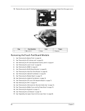
...the Lower Case" on page 64. 7. See "Removing the PC and ExpressCard dummy cards" on the main board. See "Removing the CPU" on page 75. 15. See "Removing the Middle Cover and the Power Board" on page 73. 13. See "Separating the Upper Case from the BLUE1 connector on page 61. 4. ...Chapter 3 89 See "Removing the WLAN Board Modules" on page 82. 18. See "Removing the Modem Board" on page 60. 2. See "Removing the Battery Pack"...
...the Lower Case" on page 64. 7. See "Removing the PC and ExpressCard dummy cards" on the main board. See "Removing the CPU" on page 75. 15. See "Removing the Middle Cover and the Power Board" on page 73. 13. See "Separating the Upper Case from the BLUE1 connector on page 61. 4. ...Chapter 3 89 See "Removing the WLAN Board Modules" on page 82. 18. See "Removing the Modem Board" on page 60. 2. See "Removing the Battery Pack"...

TravelMate 5520G Service Guide
Page 101
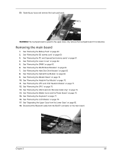
See "Removing the Optical Drive Module" on page 70. 10. See "Removing the Modem Board" on page 66. 9. See "Removing the VGA board (for Discrete model only)" on page 62. 5. See "Separating the Upper Case from the latches. See "Removing the Lower Cover" on page 74. 14. See "... cables from the Lower Case" on page 89. 19. See "Removing the WLAN Board Modules" on page 60. 3. See "Removing the CPU" on page 75. 15. See "Removing the Middle Cover and the Power Board" on page 73. 13. See "Removing the main board" on page 82. 18. Removing the Speaker Modules 1. Chapter 3 91
See "Removing the Optical Drive Module" on page 70. 10. See "Removing the Modem Board" on page 66. 9. See "Removing the VGA board (for Discrete model only)" on page 62. 5. See "Separating the Upper Case from the latches. See "Removing the Lower Cover" on page 74. 14. See "... cables from the Lower Case" on page 89. 19. See "Removing the WLAN Board Modules" on page 60. 3. See "Removing the CPU" on page 75. 15. See "Removing the Middle Cover and the Power Board" on page 73. 13. See "Removing the main board" on page 82. 18. Removing the Speaker Modules 1. Chapter 3 91

TravelMate 5520G Service Guide
Page 102
... page 77. 16. See "Removing the CPU" on page 74. 14. See "Removing the VGA board (for Discrete model only)" on page 73. 13. 21. See "Removing the Middle Cover and the Power Board" on page 79. 17. See "Removing the LCD Module" on page 75. 15. Step 1~4 ...Size (Quantity) M2 x L4 (4) Color Silver 22. Torque 1.6 kgf-cm Removing the USB Board 1. See "Removing the SD dummy card" on page 64....
... page 77. 16. See "Removing the CPU" on page 74. 14. See "Removing the VGA board (for Discrete model only)" on page 73. 13. 21. See "Removing the Middle Cover and the Power Board" on page 79. 17. See "Removing the LCD Module" on page 75. 15. Step 1~4 ...Size (Quantity) M2 x L4 (4) Color Silver 22. Torque 1.6 kgf-cm Removing the USB Board 1. See "Removing the SD dummy card" on page 64....
TravelMate 5520G Service Guide
Page 105
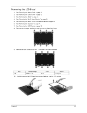
... open the LCD bezel and remove the bezel from the LCD module. Removing the LCD Bezel 1. See "Removing the WLAN Board Modules" on page 77. 7. See "Removing the Middle Cover and the Power Board" on the LCD module in the order as shown. Step 1~8 Size (Quantity) M2.5 x L6 (8) Color Black Torque 3.0 kgf-cm...
... open the LCD bezel and remove the bezel from the LCD module. Removing the LCD Bezel 1. See "Removing the WLAN Board Modules" on page 77. 7. See "Removing the Middle Cover and the Power Board" on the LCD module in the order as shown. Step 1~8 Size (Quantity) M2.5 x L6 (8) Color Black Torque 3.0 kgf-cm...
TravelMate 5520G Service Guide
Page 106
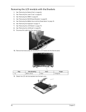
See "Removing the Middle Cover and the Power Board" on page 60. 2. See "Removing the Battery Pack" on page 75. 6. See "Removing the Lower Cover" on page 64. 5. See "Removing the WLAN Board Modules" on page 62. 3. See "Removing the Keyboard" on page 95. 9. See "Removing the LCD Bezel" on ...Step 1~3 Size (Quantity) M2.5 x L5 (3) Color Silver 11. Torque 2.5 kgf-cm 96 Chapter 3 Removing the LCD module with the brackets from the camera board. 10. See "Removing the DIMM" on page 79. 8. See "Removing the LCD Module" on page 63. 4. Remove the three screws (E) securing the LCD...
See "Removing the Middle Cover and the Power Board" on page 60. 2. See "Removing the Battery Pack" on page 75. 6. See "Removing the Lower Cover" on page 64. 5. See "Removing the WLAN Board Modules" on page 62. 3. See "Removing the Keyboard" on page 95. 9. See "Removing the LCD Bezel" on ...Step 1~3 Size (Quantity) M2.5 x L5 (3) Color Silver 11. Torque 2.5 kgf-cm 96 Chapter 3 Removing the LCD module with the brackets from the camera board. 10. See "Removing the DIMM" on page 79. 8. See "Removing the LCD Module" on page 63. 4. Remove the three screws (E) securing the LCD...
TravelMate 5520G Service Guide
Page 107
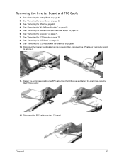
See "Removing the Middle Cover and the Power Board" on page 96. 10. See "Removing the LCD module with the Brackets" on page 75. 6. See "Removing the WLAN Board Modules" on page 95. 9. See "Removing the LCD Bezel" on page 64. 5. Disconnect the inverter board cable from the LCD panel. Chapter 3 97 See "...See "Removing the DIMM" on page 60. 2. Disconnect the FPC cable from its connector, then disconnect the 2P cable on page 79. 8. Removing the Inverter Board and FPC Cable 1. See "Removing the Battery Pack" on page 63. 4. See "Removing the LCD Module" on the inverter...
See "Removing the Middle Cover and the Power Board" on page 96. 10. See "Removing the LCD module with the Brackets" on page 75. 6. See "Removing the WLAN Board Modules" on page 95. 9. See "Removing the LCD Bezel" on page 64. 5. Disconnect the inverter board cable from the LCD panel. Chapter 3 97 See "...See "Removing the DIMM" on page 60. 2. Disconnect the FPC cable from its connector, then disconnect the 2P cable on page 79. 8. Removing the Inverter Board and FPC Cable 1. See "Removing the Battery Pack" on page 63. 4. See "Removing the LCD Module" on the inverter...

TravelMate 5520G Service Guide
Page 108
... page 75. 6. Remove the eight screws (F) securing the left and right LCD brackets to remove the brackets. See "Removing the Middle Cover and the Power Board" on page 63. 4. See "Removing the LCD Bezel" on page 62. 3. See "Removing the Lower Cover" on page 95. 9. See "Removing the WLAN... page 75. 6. See "Removing the LCD module with the Brackets" on page 96. 10. See "Removing the Middle Cover and the Power Board" on page 64. 5. See "Removing the Inverter Board and FPC Cable" on page 62. 3. See "Removing the Lower Cover" on page 97. 11. See "Removing the DIMM" on page...
... page 75. 6. Remove the eight screws (F) securing the left and right LCD brackets to remove the brackets. See "Removing the Middle Cover and the Power Board" on page 63. 4. See "Removing the LCD Bezel" on page 62. 3. See "Removing the Lower Cover" on page 95. 9. See "Removing the WLAN... page 75. 6. See "Removing the LCD module with the Brackets" on page 96. 10. See "Removing the Middle Cover and the Power Board" on page 64. 5. See "Removing the Inverter Board and FPC Cable" on page 62. 3. See "Removing the Lower Cover" on page 97. 11. See "Removing the DIMM" on page...
TravelMate 5520G Service Guide
Page 109
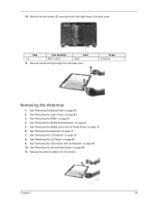
...79. 8. See "Removing the LCD Module" on page 63. 4. See "Removing the Left and Right Hinge" on page 64. 5. See "Removing the WLAN Board Modules" on page 98. 11. See "Removing the LCD module with the Brackets" on page 95. 9. Remove the left and right hinge to the back.... See "Removing the LCD Bezel" on page 96. 10. See "Removing the Battery Pack" on page 75. 6. See "Removing the Middle Cover and the Power Board" on page 60. 2. Release the antenna cables from the back cover. Torque 2.5 kgf-cm Removing the Antennas 1. See "Removing the Keyboard" on page 62....
...79. 8. See "Removing the LCD Module" on page 63. 4. See "Removing the Left and Right Hinge" on page 64. 5. See "Removing the WLAN Board Modules" on page 98. 11. See "Removing the LCD module with the Brackets" on page 95. 9. Remove the left and right hinge to the back.... See "Removing the LCD Bezel" on page 96. 10. See "Removing the Battery Pack" on page 75. 6. See "Removing the Middle Cover and the Power Board" on page 60. 2. Release the antenna cables from the back cover. Torque 2.5 kgf-cm Removing the Antennas 1. See "Removing the Keyboard" on page 62....
TravelMate 5520G Service Guide
Page 110
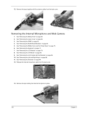
..." on page 95. 9. Remove the tape holding the internal microphone in place. 100 Chapter 3 See "Removing the DIMM" on page 64. 5. See "Removing the WLAN Board Modules" on page 63. 4. 12. See "Removing the Battery Pack" on page 98. 11. See "Removing the Left and Right Hinge" on page 60. 2. Release... the back cover. Removing the Internal Microphone and Web Camera 1. See "Removing the LCD Module" on page 75. 6. See "Removing the Middle Cover and the Power Board" on page 79. 8.
..." on page 95. 9. Remove the tape holding the internal microphone in place. 100 Chapter 3 See "Removing the DIMM" on page 64. 5. See "Removing the WLAN Board Modules" on page 63. 4. 12. See "Removing the Battery Pack" on page 98. 11. See "Removing the Left and Right Hinge" on page 60. 2. Release... the back cover. Removing the Internal Microphone and Web Camera 1. See "Removing the LCD Module" on page 75. 6. See "Removing the Middle Cover and the Power Board" on page 79. 8.
TravelMate 5520G Service Guide
Page 142
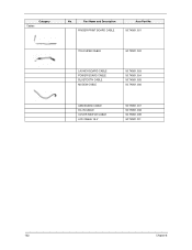
Part Name and Description FINGER PRINT BOARD CABLE Acer Part No. 50.TK901.001 TOUCHPAD CABLE 50.TK901.002 LAUNCH BOARD CABLE POWER BOARD CABLE BLUETOOTH CABLE MODEM CABLE 50.TK901.003 50.TK901.004 50.TK901.005 50.TK901.006 USB BOARD CABLE DC-IN CABLE COVER SWITCH CABLE LCD CABLE 15.4" 50.TK901.007 50.TK901.008 50.TK901.009 50.TK901.011 132 Chapter 6 Cables Category No.
Part Name and Description FINGER PRINT BOARD CABLE Acer Part No. 50.TK901.001 TOUCHPAD CABLE 50.TK901.002 LAUNCH BOARD CABLE POWER BOARD CABLE BLUETOOTH CABLE MODEM CABLE 50.TK901.003 50.TK901.004 50.TK901.005 50.TK901.006 USB BOARD CABLE DC-IN CABLE COVER SWITCH CABLE LCD CABLE 15.4" 50.TK901.007 50.TK901.008 50.TK901.009 50.TK901.011 132 Chapter 6 Cables Category No.
TravelMate 5520G Service Guide
Page 180
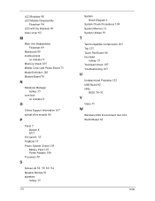
...Brackets 96 lower cover 62 M Main Unit Disassembly Flowchart 69 Mainboard 89 media access on indicator 9 Memory Check 105 Middle Cover and Power Board 75 Model Definition 140 Modem Board 70 N Notebook Manager hotkey 15 num lock on indicator 9 O Online Support Information 167 optical drive module 66 P Panel 5 ...Bottom 8 left 5 PC Card 9, 35 PCMCIA 35 Power System Check 105 Battery Pack 107 Power Adapter 106 Processor 30 S Screw List 58, 59, ...
...Brackets 96 lower cover 62 M Main Unit Disassembly Flowchart 69 Mainboard 89 media access on indicator 9 Memory Check 105 Middle Cover and Power Board 75 Model Definition 140 Modem Board 70 N Notebook Manager hotkey 15 num lock on indicator 9 O Online Support Information 167 optical drive module 66 P Panel 5 ...Bottom 8 left 5 PC Card 9, 35 PCMCIA 35 Power System Check 105 Battery Pack 107 Power Adapter 106 Processor 30 S Screw List 58, 59, ...


