Service Guide
Page 7
... 31 Removing the Heat Sink Fan Assembly 32 Removing the Processor 34 Removing the Optical Drive 36 Removing the Hard Disk Drive 38 Removing the Power Supply 41 Removing the Memory Modules 44 Removing the PCI Card 45 Removing the Front I/O and Card Reader Boards 47 Removing the Mainboard 51 System Troubleshooting... System Block Diagram and Board Layout 63 System Block Diagram 63 Board Layout 64 Mainboard 64 System Jumpers 65 FRU (Field Replaceable Unit) List 67 EL1210 Exploded Diagram 68 EL1210 FRU List (81.3V801.007G) 69 Technical Specifications 73 vii
... 31 Removing the Heat Sink Fan Assembly 32 Removing the Processor 34 Removing the Optical Drive 36 Removing the Hard Disk Drive 38 Removing the Power Supply 41 Removing the Memory Modules 44 Removing the PCI Card 45 Removing the Front I/O and Card Reader Boards 47 Removing the Mainboard 51 System Troubleshooting... System Block Diagram and Board Layout 63 System Block Diagram 63 Board Layout 64 Mainboard 64 System Jumpers 65 FRU (Field Replaceable Unit) List 67 EL1210 Exploded Diagram 68 EL1210 FRU List (81.3V801.007G) 69 Technical Specifications 73 vii
Service Guide
Page 10
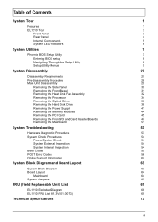
...: Genuine Windows Vista® Ultimate (32/64-bit) Genuine Windows Vista Home Premium (32/64-bit) Applications Acer Empowering Technology (Acer eRecovery Management) Acer Arcade Live McAfee Internet Security Suite 2008 Trial version Adobe Reader eSobi NTI MediaMaker Power supply 220-watts (115/230 Vac...
...: Genuine Windows Vista® Ultimate (32/64-bit) Genuine Windows Vista Home Premium (32/64-bit) Applications Acer Empowering Technology (Acer eRecovery Management) Acer Arcade Live McAfee Internet Security Suite 2008 Trial version Adobe Reader eSobi NTI MediaMaker Power supply 220-watts (115/230 Vac...

Service Guide
Page 13
Component 1 Expansion card 2 Mainboard 3 Heat sink fan assembly 4 Power supply 5 Optical drive Chapter 1 5 Internal Components No.
Component 1 Expansion card 2 Mainboard 3 Heat sink fan assembly 4 Power supply 5 Optical drive Chapter 1 5 Internal Components No.
Service Guide
Page 37
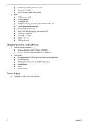
Main Unit Disassembly MAIN UNIT DISASSEMBLY MAIN UNIT Ax2 SIDE PANEL FRONT BEZEL HEAT SINK FAN ASSEMBLY CPU Bx1 OPTICAL DISK DRIVE Cx1 HDD-ODD BRACKET Ax3 Cx1 POWER SUPPLY Dx4 HDD MODULE HDD MEMORY MODULES Ex1 PCI CARD Dx2 FRONT I/O AND CARD READER BOARD BRACKET Cx6 MAINBOARD Cx2 FRONT I/O BOARD Cx2 CARD READER BOARD Screw List A B C D E Chapter 3 Screw #6-32 L5 BZN M3xL5 BZN #6-32 L6 NI #6-32*3/16 NI #6-32 5MM NI Part No. 86.00J07.B60 86.1A324.5R0 86.00J44.C60 86.5A5B6.012 86.9A5G6.162 29
Main Unit Disassembly MAIN UNIT DISASSEMBLY MAIN UNIT Ax2 SIDE PANEL FRONT BEZEL HEAT SINK FAN ASSEMBLY CPU Bx1 OPTICAL DISK DRIVE Cx1 HDD-ODD BRACKET Ax3 Cx1 POWER SUPPLY Dx4 HDD MODULE HDD MEMORY MODULES Ex1 PCI CARD Dx2 FRONT I/O AND CARD READER BOARD BRACKET Cx6 MAINBOARD Cx2 FRONT I/O BOARD Cx2 CARD READER BOARD Screw List A B C D E Chapter 3 Screw #6-32 L5 BZN M3xL5 BZN #6-32 L6 NI #6-32*3/16 NI #6-32 5MM NI Part No. 86.00J07.B60 86.1A324.5R0 86.00J44.C60 86.5A5B6.012 86.9A5G6.162 29

Service Guide
Page 49
See "Removing the Side Panel" on page 32. 4. Chapter 3 41 See "Removing the Heat Sink Fan Assembly" on page 30. 2. See "Removing the Optical Drive" on page 34. 5. See "Removing the Processor" on page 36. 6. Disconnect the 4-pin and 24-pin power supply cables from the mainboard. Removing the Power Supply 1. See "Removing the Hard Disk Drive" on page 31. 3. See "Removing the Front Bezel" on page 38. 7.
See "Removing the Side Panel" on page 32. 4. Chapter 3 41 See "Removing the Heat Sink Fan Assembly" on page 30. 2. See "Removing the Optical Drive" on page 34. 5. See "Removing the Processor" on page 36. 6. Disconnect the 4-pin and 24-pin power supply cables from the mainboard. Removing the Power Supply 1. See "Removing the Hard Disk Drive" on page 31. 3. See "Removing the Front Bezel" on page 38. 7.

Service Guide
Page 50
Screw (Quantity) #6-32 L5 BZN (3) Color Black Torque 5.5 to 6.5 kgf-cm Part No. 86.00J44.C60 9. Screw (Quantity) #6-32 L6 BZN (1) Color Silver Torque 5.5 to 6.5 kgf-cm Part No. 86.00J07.B60 42 Chapter 3 8. Remove the screw (C) that secure the power supply to the chassis. Remove the three screws (A) that secures the power supply to the rear panel.
Screw (Quantity) #6-32 L5 BZN (3) Color Black Torque 5.5 to 6.5 kgf-cm Part No. 86.00J44.C60 9. Screw (Quantity) #6-32 L6 BZN (1) Color Silver Torque 5.5 to 6.5 kgf-cm Part No. 86.00J07.B60 42 Chapter 3 8. Remove the screw (C) that secure the power supply to the chassis. Remove the three screws (A) that secures the power supply to the rear panel.

Service Guide
Page 51
10. Lift the power supply module out of the chassis. Chapter 3 43
10. Lift the power supply module out of the chassis. Chapter 3 43


