Service Guide
Page 12
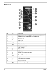
Rear Panel No. Icon 1 2 3 4 5 6 7 8 9 10 11 12 13 14 15 16 Component Expansion slot (Photo shows graphics card and network/modem card) Headphone/analog speakers jack or front speakers jack Microphone jack USB 2.0 ports CRT/LCD monitor port PS2 keyboard port Voltage selector switch Power connector PS2 mouse port USB 2.0 ports Gigabit LAN port (10/100/1000 Mbps) Surround L/R speaker jack Keyhole Center speaker/subwoofer jack Kensington lock slot Audio in or side speaker jack 4 Chapter 1
Rear Panel No. Icon 1 2 3 4 5 6 7 8 9 10 11 12 13 14 15 16 Component Expansion slot (Photo shows graphics card and network/modem card) Headphone/analog speakers jack or front speakers jack Microphone jack USB 2.0 ports CRT/LCD monitor port PS2 keyboard port Voltage selector switch Power connector PS2 mouse port USB 2.0 ports Gigabit LAN port (10/100/1000 Mbps) Surround L/R speaker jack Keyhole Center speaker/subwoofer jack Kensington lock slot Audio in or side speaker jack 4 Chapter 1
Service Guide
Page 19
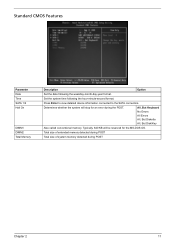
... detected during POST Total size of system memory detected during the POST. Determines whether the system will be reserved for an error during POST Chapter 2 11 Standard CMOS Features Parameter Date Time SATA 1/2 Halt On DIMM1 DIMM2 Total Memory Description Option Set the date following the hour-minute-second format. All...
... detected during POST Total size of system memory detected during the POST. Determines whether the system will be reserved for an error during POST Chapter 2 11 Standard CMOS Features Parameter Date Time SATA 1/2 Halt On DIMM1 DIMM2 Total Memory Description Option Set the date following the hour-minute-second format. All...
Service Guide
Page 56
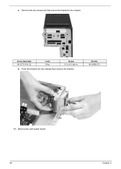
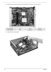
Remove the two screws (D) that secure the bracket to 6.5 kgf-cm b. Screw (Quantity) #6-32*3/16 NI (2) Color Silver Torque 5.5 to the chassis. Push the bracket into the chassis then remove the bracket. a. Part No. 86.5A5B6.012 11. Remove the card reader board. 48 Chapter 3
Remove the two screws (D) that secure the bracket to 6.5 kgf-cm b. Screw (Quantity) #6-32*3/16 NI (2) Color Silver Torque 5.5 to the chassis. Push the bracket into the chassis then remove the bracket. a. Part No. 86.5A5B6.012 11. Remove the card reader board. 48 Chapter 3
Service Guide
Page 60
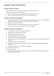
Torque 5.5 to the chassis, in the order shown. 11. Remove the six screws (C) that secure the mainboard to 6.5 kgf-cm Part No. 86.00J44.C60 52 Chapter 3 Screw (Quantity) #6-32 L5 BZN (6) Color Silver 12. Lift the board from the chassis.
Torque 5.5 to the chassis, in the order shown. 11. Remove the six screws (C) that secure the mainboard to 6.5 kgf-cm Part No. 86.00J44.C60 52 Chapter 3 Screw (Quantity) #6-32 L5 BZN (6) Color Silver 12. Lift the board from the chassis.
Service Guide
Page 62
...behaviour, see "System LED Indicators" on page 25. 7. Verify that all the peripherals connected to System External Inspection. Replace the system covers. 11. Make sure that could short out power. 4. System External Inspection 1. Unplug the power cord from the power outlets. 3. Remove the system covers...in the system is not evident, you can indicate the malfunction. Verify that all peripheral cables from the system. 5. Verify that components are Acer-qualified and supported. 10. Power on , do the following: Check if the power cable is properly connected to the system ...
...behaviour, see "System LED Indicators" on page 25. 7. Verify that all the peripherals connected to System External Inspection. Replace the system covers. 11. Make sure that could short out power. 4. System External Inspection 1. Unplug the power cord from the power outlets. 3. Remove the system covers...in the system is not evident, you can indicate the malfunction. Verify that all peripheral cables from the system. 5. Verify that components are Acer-qualified and supported. 10. Power on , do the following: Check if the power cable is properly connected to the system ...
Service Guide
Page 72
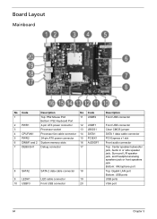
Board Layout Mainboard No Code Description No Code 1 Top: PS2 Mouse Port 11 USBF2 Bottom: PS2 Keyboard Port 2 PWR1 4-pin ATX power connector 12 USBF1 3 Processor socket 13 JBIOS1 4 CPUFAN1 Processor fan cable connector 14 SATA1 5 PWR2 24-...
Board Layout Mainboard No Code Description No Code 1 Top: PS2 Mouse Port 11 USBF2 Bottom: PS2 Keyboard Port 2 PWR1 4-pin ATX power connector 12 USBF1 3 Processor socket 13 JBIOS1 4 CPUFAN1 Processor fan cable connector 14 SATA1 5 PWR2 24-...

