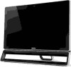
Acer Aspire ZS600 Desktop Service Guide
Page 5
... 3-6 Disassembly Flowchart 3-7 Removing the Stand 3-9 Removing the Rear Cover 3-11 Removing the HDD 3-15 Removing the Converter Board 3-16 Removing the ODD 3-17 Removing the Camera 3-19 Removing the OSD Board 3-20 Removing the Motherboard Shielding 3-21 Removing the Display Card 3-23 Removing the Memory 3-26 ii-v
Acer Aspire ZS600 Desktop Service Guide
Page 6
... Replacing the Display Card 3-75 Replacing the Speaker 3-77 Replacing the Touchpad 3-79 Replacing the TV Tuner 3-81 Replacing the OSD Board 3-82 Replacing the Camera 3-83 Replacing the ODD 3-85 Replacing the Converter Board 3-87 Replacing the HDD 3-90 Replacing the Heatsink 3-92 Replacing the Motherboard Shielding 3-94 Replacing the...
Acer Aspire ZS600 Desktop Service Guide
Page 24
System Tour 0 Table 1-2. Front View No Icon Item 1 IR Port 2 Webcam 3 Speaker 4 Power button Description Port to receive IR signal Web camera for video communication Deliver stereo audio output Turns the computer on and off. 1-16 Hardware Specifications and Configurations
Acer Aspire ZS600 Desktop Service Guide
Page 25
...) Connects to audio devices(eg., speakers, Jack headphones). 6 Microphone Jack Accepts inputs from external microphones. JP SKU only Connects to USB 3.0 devices (e.g., USB mouse, USB camera). 5 Headphone/speaker Connects to USB 3.0 devices (e.g., USB mouse, USB...
Acer Aspire ZS600 Desktop Service Guide
Page 27
Rear View No Icon Item 1 Coaxial connector 2 SPDIF connector 3 USB 2.0 ports Description Connects to a TV Connects to SPDIF Connects to USB 2.0 devices (e.g., USB mouse, USB camera). 4 USB 2.0 ports Connects to USB 2.0 devices (e.g., USB mouse, USB camera). 5 Ethernet (RJ-45) port Connects to an Ethernet 10/100/1000-based network. 6 HDMI port Supports high definition digital video connections. Table 1-5. Hardware Specifications and Configurations 1-19
Acer Aspire ZS600 Desktop Service Guide
Page 30
... OUT speaker MIC Head phone Side USB3.0-2 SIM connector Side USB3.0-1(Charge port) Card reader connector Mini PCIE Slot1 Mini PCIE Slot2 CIR header Web Camera header BIOS WP CLEAR CMOS DIMM1 DIMM2 CPU socket Jumper Setting 0 This section explains how to have the correct configuration for jumper setting on the...
Acer Aspire ZS600 Desktop Service Guide
Page 78
... Antenna Cables 3-51 Remove the Cushion Tape 3-53 Remove the Thermal Pads 3-54 Remove the LVDS Cable 3-55 Remove the Base Pan 3-56 Remove the Camera 3-58 Remove the Backlight Cable 3-59 Remove the IR Cable 3-60 Remove the Front Bezel 3-61 Reassembly Procedure 3-62 Reassembly Flowchart 3-62 Replace the LCD... Module 3-63 Replace the Backlight Cable 3-65 Replace the Camera 3-66 Replace the LVDS Cable 3-67 Replace the WLAN Antenna Cables 3-68 Replace the OSD Board 3-70 3-2
Acer Aspire ZS600 Desktop Service Guide
Page 113
Camera Cable 2. VGA Bracket Table 3-16. Lift to remove VGA bracket. Remove 2 screws on VGA bracket. Screws Step Screw VGA Bracket Removal M3*5 3. Quantity 2 Screw Type 3-37 Figure 3-50. Figure 3-49. Disconnect camera cable from motherboard, tear off the acetate fabric from the VGA bracket. Remove the VGA Bracket 0 1.
Acer Aspire ZS600 Desktop Service Guide
Page 134
Camera 2. Lift to remove CMOS camera together with camera cable from CMOS camera. Figure 3-85. Disconnect camera cable from front bezel. Figure 3-86. Camera 3-58 Remove the Camera 0 1.
Acer Aspire ZS600 Desktop Service Guide
Page 142
Figure 3-97. Camera Module 3-66 Connect webcam cable to the camera, position the camera module on front bezel with the lens downward. Replace the Camera 0 1.
Acer Aspire ZS600 Desktop Service Guide
Page 168
Replace the Convert Board 0 1. Route camera cable and LVDS cable under the metal hook of base pan. 3-92 Route camera cable under metal hooks of base pan. Camera Cable 2. Camera Cable 3. Figure 3-137. Figure 3-138. Adhere the acetate fabric to fix camera cable.
Acer Aspire ZS600 Desktop Service Guide
Page 169
Position the convert board on base pan, consolidate it under metal hooks of acetate fabric to convert board and route it with 2 screws. Figure 3-140. Connect camera cable to motherboard, adhere 2 pieces of base pan. 3-93 Camera Cable 5. Connect the convert cable to fix the cable. Camera Cable and LVDS Cable 4. Figure 3-139.
Acer Aspire ZS600 Desktop Service Guide
Page 230
Table 6-1. Item 31 Part Name TVT ATSC H334 HYBRID W/APP-A PARIS 23 COAXIAL CAP 32 IPISB-AG/UMA/USB3/HS/RAY 33 PARIS 23 VGA LOCK 34 PARIS A 23 SIDE IO DOOR F-C 35 PARIS_II A 23 BASE PAN SUB ASM 36 COMS CAMERA 1920*1080 37 PARIS A 23 BKT FRONTSTAND LEFT 38 WLAN CBL 1P L:300mm AM8-10 39 PARIS_II A 23 FRONT BEZEL ASM 40 PARIS_II A 23 PANEL BKT L 41 PARIS_II A 23 PANEL BKT U 42 LCD TF 23' FHD WLED 43 TOUCH GLASS 23' PCT 07 44 TOUCH CONTROLLER 23' PCT 07 Memo WITH TV TUNER W/O TV TUNER 6-6 FRU (Field Replaceable Unit) List