Service Guide
Page 7
... Back Cover 48 Removing the Hinge 50 Removing the Mainboard Shielding 51 Removing the Hard Disk Drive 55 Removing the Power Supply 58 Removing the Touchscreen Control Board 59 Removing the Card Reader Board 62 Removing the Audio Board 63 Removing the ODD Eject Board 65 Removing the ODD 67 69...
... Back Cover 48 Removing the Hinge 50 Removing the Mainboard Shielding 51 Removing the Hard Disk Drive 55 Removing the Power Supply 58 Removing the Touchscreen Control Board 59 Removing the Card Reader Board 62 Removing the Audio Board 63 Removing the ODD Eject Board 65 Removing the ODD 67 69...

Service Guide
Page 8
... 129 Replacing the ODD Module 132 Replacing the ODD Eject Board 134 Replacing the Audio Board 135 Connect the Card Reader Board 136 Replacing the Touchscreen Board 137 Replacing the Power Supply 139 Replacing the HDD 140 Replacing the Mainboard Shielding 142 Replacing the Hinge 146 Replacing the Rear Cover 147...
... 129 Replacing the ODD Module 132 Replacing the ODD Eject Board 134 Replacing the Audio Board 135 Connect the Card Reader Board 136 Replacing the Touchscreen Board 137 Replacing the Power Supply 139 Replacing the HDD 140 Replacing the Mainboard Shielding 142 Replacing the Hinge 146 Replacing the Rear Cover 147...
Service Guide
Page 12
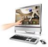
Graphics Z5710 • • • • • • • • Z5700 • NVIDIA® GeForce® G210M with 512 MB of dedicated DDR3 VRAM, supporting NVIDIA® ..." Full HD 1920 x 1080 pixel resolution, high brightness (300-nit), TFT LCD 16:9 aspect ratio 5 ms response time 16.7 million colors 1000:1 (ACM) contrast ratio Touchscreen • Integrated Windows® 7 compliant multi-touch capable optical solution Hard drive Hard disk drive • 500/640/750 GB / 1 TB 7200 RPM • 1/1.5/2 TB...
Graphics Z5710 • • • • • • • • Z5700 • NVIDIA® GeForce® G210M with 512 MB of dedicated DDR3 VRAM, supporting NVIDIA® ..." Full HD 1920 x 1080 pixel resolution, high brightness (300-nit), TFT LCD 16:9 aspect ratio 5 ms response time 16.7 million colors 1000:1 (ACM) contrast ratio Touchscreen • Integrated Windows® 7 compliant multi-touch capable optical solution Hard drive Hard disk drive • 500/640/750 GB / 1 TB 7200 RPM • 1/1.5/2 TB...

Service Guide
Page 25
..., DBPSK and CCK (b) 2412 ~ 2484MHz ISM band 1---14 channels for active channels 802.11b data rate: 11,5.5,2,1 Mbps with various capacities to +80°C Touchscreen Item Touchscreen Specifications Windows 7 multitouch and gestures Chapter 1 15 USB Port Chipset Item SB710 embedded Specification USB compliance level OHCI Number of slot 1 and slot 2 could be...
..., DBPSK and CCK (b) 2412 ~ 2484MHz ISM band 1---14 channels for active channels 802.11b data rate: 11,5.5,2,1 Mbps with various capacities to +80°C Touchscreen Item Touchscreen Specifications Windows 7 multitouch and gestures Chapter 1 15 USB Port Chipset Item SB710 embedded Specification USB compliance level OHCI Number of slot 1 and slot 2 could be...
Service Guide
Page 50
... to any surface it is removed. Unplug the AC adapter and all peripherals. 2. Chapter 3 Machine Disassembly and Replacement WARNING:This computer has two highly sensitive touchscreen sensors on the top left and right corners of the sequence to avoid damage to the system and all power and signal cables from the...
... to any surface it is removed. Unplug the AC adapter and all peripherals. 2. Chapter 3 Machine Disassembly and Replacement WARNING:This computer has two highly sensitive touchscreen sensors on the top left and right corners of the sequence to avoid damage to the system and all power and signal cables from the...
Service Guide
Page 52
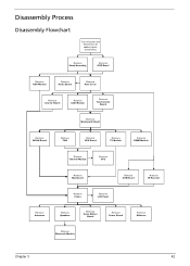
... cables before proceeding Remove Stand Assembly Remove ODD Bezel Remove HDD Module Remove Audio Board Remove Rear Cover Remove Inverter Board Remove ODD Module Remove Touchscreen Board Remove Mainboard Shield Remove WLAN Board Remove FAN Remove VGA Board Remove TV Module Remove DIMM Module Remove Thermal Module Remove CPU Remove Mainboard...
... cables before proceeding Remove Stand Assembly Remove ODD Bezel Remove HDD Module Remove Audio Board Remove Rear Cover Remove Inverter Board Remove ODD Module Remove Touchscreen Board Remove Mainboard Shield Remove WLAN Board Remove FAN Remove VGA Board Remove TV Module Remove DIMM Module Remove Thermal Module Remove CPU Remove Mainboard...
Service Guide
Page 53
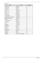
Screw List Step Stand Cover Stand Hinge Rear Cover Audio Board HDD HDD Bracket ODD ODD Brackets Inverter Board Touchscreen Control Board Mainboard Shielding WLAN TV Tuner Module VGA Card Fan Mainboard USB Board IR Receiver Frame LCD Panel Power Board Camera Antennas Speakers Screw M2.5*4 M4*6 Ni M2.5*7 M2.5*4 Ni M2.5*4 Ni M3*4 Ni M2.5*4 Ni M2*2.5 Ni M2.5*4 Ni M2.5*4 Ni M2.5*4 Ni M2*3 M2.5*4 Ni M2.5*4 Ni M2.5*5 Ni M2.5*4 Ni M2.5*4 Ni M2*3 M2.5*4 Ni M3*4 M2.5*4 Ni M2*3 M1.7*4 M2.5*4.0-I(NYLOK)IRON Quantity 2 4 4 2 2 4 2 4 2 2 7 1 1 4 3 1 2 1 15 4 2 2 2 6 43 Chapter 3
Screw List Step Stand Cover Stand Hinge Rear Cover Audio Board HDD HDD Bracket ODD ODD Brackets Inverter Board Touchscreen Control Board Mainboard Shielding WLAN TV Tuner Module VGA Card Fan Mainboard USB Board IR Receiver Frame LCD Panel Power Board Camera Antennas Speakers Screw M2.5*4 M4*6 Ni M2.5*7 M2.5*4 Ni M2.5*4 Ni M3*4 Ni M2.5*4 Ni M2*2.5 Ni M2.5*4 Ni M2.5*4 Ni M2.5*4 Ni M2*3 M2.5*4 Ni M2.5*4 Ni M2.5*5 Ni M2.5*4 Ni M2.5*4 Ni M2*3 M2.5*4 Ni M3*4 M2.5*4 Ni M2*3 M1.7*4 M2.5*4.0-I(NYLOK)IRON Quantity 2 4 4 2 2 4 2 4 2 2 7 1 1 4 3 1 2 1 15 4 2 2 2 6 43 Chapter 3

Service Guide
Page 58
Use both hands to lift the Back Cover away, the Hinge must be in position. Remove the fourteen (14) screws securing the Back Cover. Step Back Cover 2.5*8 Size Quantity Screw Type 2.4*8 3. See "Removing the Touchscreen Control Board" on page 59 2. There is an audible click when the Hinge is locked in the stand position. Chapter 3 48 NOTE: In order to move the Hinge up into the stand position. Removing the Back Cover 1.
Use both hands to lift the Back Cover away, the Hinge must be in position. Remove the fourteen (14) screws securing the Back Cover. Step Back Cover 2.5*8 Size Quantity Screw Type 2.4*8 3. See "Removing the Touchscreen Control Board" on page 59 2. There is an audible click when the Hinge is locked in the stand position. Chapter 3 48 NOTE: In order to move the Hinge up into the stand position. Removing the Back Cover 1.

Service Guide
Page 61
Removing the Mainboard Shielding 1. See "Removing the Audio Board" on page 59. 3. Remove the one (1) screw from the mainboard. See "Removing the Touchscreen Control Board" on page 63. 2. Remove the small power cable from the ground wire. Step HDD Ground Cable Size M2.5*4 Quantity 1 4. Screw Type 51 Chapter 3
Removing the Mainboard Shielding 1. See "Removing the Audio Board" on page 59. 3. Remove the one (1) screw from the mainboard. See "Removing the Touchscreen Control Board" on page 63. 2. Remove the small power cable from the ground wire. Step HDD Ground Cable Size M2.5*4 Quantity 1 4. Screw Type 51 Chapter 3

Service Guide
Page 69
See "Removing the Back Cover" on page 48 2. Quantity 1 Screw Type 59 Chapter 3 Disconnect the right (top in this image) touch sensor cable. Remove the one (1) ground cable screw. Step Touchscreen Control Board M2.5*4 Size 3. Removing the Touchscreen Control Board 1.
See "Removing the Back Cover" on page 48 2. Quantity 1 Screw Type 59 Chapter 3 Disconnect the right (top in this image) touch sensor cable. Remove the one (1) ground cable screw. Step Touchscreen Control Board M2.5*4 Size 3. Removing the Touchscreen Control Board 1.

Service Guide
Page 70
Remove the two (2) screws. Disconnect the left (bottom in this image) touch sensor cable. 5. Step Touchscreen Board Size M2.0*4 Quantity 2 Screw Type Chapter 3 60 4. Disconnect the touchscreen board to mainboard cable. 6.
Remove the two (2) screws. Disconnect the left (bottom in this image) touch sensor cable. 5. Step Touchscreen Board Size M2.0*4 Quantity 2 Screw Type Chapter 3 60 4. Disconnect the touchscreen board to mainboard cable. 6.

Service Guide
Page 71
7. Lift the touchscreen board away. 61 Chapter 3
7. Lift the touchscreen board away. 61 Chapter 3

Service Guide
Page 99
See "Removing the Frame" on page 85. 4. Remove the LVDS connector protective cover. 89 Chapter 3 See "Removing the Mainboard" on page 89. 5. Remove the adhesive tape holding the LVDS cable to the LCD bracket. 7. See "Removing the Touchscreen Control Board" on page 89. 6. See "Removing the Frame" on page 59. 3. Removing the Frame 1. See "Removing the Mainboard Shielding" on page 51. 2.
See "Removing the Frame" on page 85. 4. Remove the LVDS connector protective cover. 89 Chapter 3 See "Removing the Mainboard" on page 89. 5. Remove the adhesive tape holding the LVDS cable to the LCD bracket. 7. See "Removing the Touchscreen Control Board" on page 89. 6. See "Removing the Frame" on page 59. 3. Removing the Frame 1. See "Removing the Mainboard Shielding" on page 51. 2.
Service Guide
Page 104
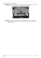
Doing so will damage the touch screen function. 15. IMPORTANT:Do not place the LCD panel face down. When following the remainder of the bezel. Lift the LCD bracket clear of the disassembly instructions, place something between the LCD face and the tabletop to prevent pressure on the touchscreen sensors. Chapter 3 94 WARNING:When lifting the LCD Assembly, do not touch the Touch sensor modules located at the top left and top right corners of the device.
Doing so will damage the touch screen function. 15. IMPORTANT:Do not place the LCD panel face down. When following the remainder of the bezel. Lift the LCD bracket clear of the disassembly instructions, place something between the LCD face and the tabletop to prevent pressure on the touchscreen sensors. Chapter 3 94 WARNING:When lifting the LCD Assembly, do not touch the Touch sensor modules located at the top left and top right corners of the device.

Service Guide
Page 106
IMPORTANT:The touchscreen control board and LCD panel must be returned together for RMA. The touchscreen control board records the specific panel's data, do not separate these for RMA purposes. Chapter 3 96 See "Removing the Touchscreen Control Board" on page 59. 4. Lift the LCD bracket away from the LCD assembly.
IMPORTANT:The touchscreen control board and LCD panel must be returned together for RMA. The touchscreen control board records the specific panel's data, do not separate these for RMA purposes. Chapter 3 96 See "Removing the Touchscreen Control Board" on page 59. 4. Lift the LCD bracket away from the LCD assembly.

Service Guide
Page 147
Replacing the Touchscreen Board 1. Replace the two (2) screws. Place the touchscreen board onto the chassis. 2. Step Touchscreen Control Board M2.5*4 Size 3. Quantity 1 Screw Type 137 Chapter 3 Connect the touchscreen board to mainboard cable.
Replacing the Touchscreen Board 1. Replace the two (2) screws. Place the touchscreen board onto the chassis. 2. Step Touchscreen Control Board M2.5*4 Size 3. Quantity 1 Screw Type 137 Chapter 3 Connect the touchscreen board to mainboard cable.
Service Guide
Page 189
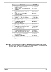
...ASSY 20 DVD R/R W/RAM 30656280 AD7643SAR STN B Acer P/N 21HYECA00Q0 23EL5CATN00 ABSE64G5004 AB721010011 3YEL5BATN00 3Q3L5BCTN00 EBEL8001010 FBEL8001010 EBEL8002010 3REL8RCTN00 EBEL8022010 FBEL8008010 ENEL5CB0000 AF250C00001 32EL5AB0000 AW07643S000 IMPORTANT: *The touchscreen control board and LCD panel must be returned together ...for RMA. See "Removing the Touchscreen Control Board" on page 59. The touchscreen control board records the specific panel's data...
...ASSY 20 DVD R/R W/RAM 30656280 AD7643SAR STN B Acer P/N 21HYECA00Q0 23EL5CATN00 ABSE64G5004 AB721010011 3YEL5BATN00 3Q3L5BCTN00 EBEL8001010 FBEL8001010 EBEL8002010 3REL8RCTN00 EBEL8022010 FBEL8008010 ENEL5CB0000 AF250C00001 32EL5AB0000 AW07643S000 IMPORTANT: *The touchscreen control board and LCD panel must be returned together ...for RMA. See "Removing the Touchscreen Control Board" on page 59. The touchscreen control board records the specific panel's data...


