

Service Guide
Page 9
Table of Contents Jumper and Connector Locations 175 Mainboard Top View 175 BIOS Recovery 176 FRU (Field Replaceable Unit) List 177 Exploded Diagrams 178 FRU List 180 Model Definition and Configuration 188 Test Compatible Components 190 Online Support Information 192 Index 193 IX
Table of Contents Jumper and Connector Locations 175 Mainboard Top View 175 BIOS Recovery 176 FRU (Field Replaceable Unit) List 177 Exploded Diagrams 178 FRU List 180 Model Definition and Configuration 188 Test Compatible Components 190 Online Support Information 192 Index 193 IX
Service Guide
Page 24
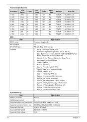
... 73W 73W 87W 73W Cache Size 4M 4M 4M 4M 4M 4M 8M 8M 8M Package FCBGA FCBGA FCBGA FCBGA FCBGA FCBGA FCBGA FCBGA FCBGA Acer P/N KC.53001.CI3 KC.54001.CI3 KC.65001.CI5 KC.66001.CI5 KC.66101.CI5 KC.67001.CI5 KC.75001.CI5 KC.86001.CI7 KC... Specification American Megatrends 3.0 16Mbits, 8 pin SOIC package • PC/AT Compatible System BIOS. • ACPI 3.0 Compliance/Support, S0, S1, S3, S4, S5. • Boot Block Recovery mode from CD-ROM/USB FDD/USB CD-
... 73W 73W 87W 73W Cache Size 4M 4M 4M 4M 4M 4M 8M 8M 8M Package FCBGA FCBGA FCBGA FCBGA FCBGA FCBGA FCBGA FCBGA FCBGA Acer P/N KC.53001.CI3 KC.54001.CI3 KC.65001.CI5 KC.66001.CI5 KC.66101.CI5 KC.67001.CI5 KC.75001.CI5 KC.86001.CI7 KC... Specification American Megatrends 3.0 16Mbits, 8 pin SOIC package • PC/AT Compatible System BIOS. • ACPI 3.0 Compliance/Support, S0, S1, S3, S4, S5. • Boot Block Recovery mode from CD-ROM/USB FDD/USB CD-
Service Guide
Page 175
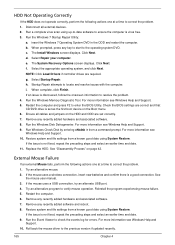
..., insert new batteries and confirm there is discovered, follow the onscreen information to ensure the computer is set correctly. 7. i. Try an alternative mouse. 2. The System Recovery Options screen displays. If an issue is a good connection. For more information see Windows Help and Support. 10. Ensure all external devices. 2. b. See "Disassembly Process...
..., insert new batteries and confirm there is discovered, follow the onscreen information to ensure the computer is set correctly. 7. i. Try an alternative mouse. 2. The System Recovery Options screen displays. If an issue is a good connection. For more information see Windows Help and Support. 10. Ensure all external devices. 2. b. See "Disassembly Process...
Service Guide
Page 178
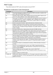
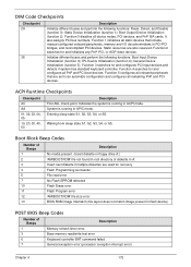
... ROM to lower system memory and control is forced. Copies BIOS from one platform to determine if BIOS recovery is given to RAM for more information. If BIOS recovery is enabled at this value may be enabled from ACPI S3 state OEM memory detection/configuration error. Store ...keyboard controller BAT test. System will be different from ROM to it . Re-enable CACHE. Performs main BIOS checksum and updates recovery status accordingly. See Bootblock Recovery Code Checkpoints section of document for future use in memory. The Runtime module is bad. Leaves all RAM below 1MB Read-Write...
... ROM to lower system memory and control is forced. Copies BIOS from one platform to determine if BIOS recovery is given to RAM for more information. If BIOS recovery is enabled at this value may be enabled from ACPI S3 state OEM memory detection/configuration error. Store ...keyboard controller BAT test. System will be different from ROM to it . Re-enable CACHE. Performs main BIOS checksum and updates recovery status accordingly. See Bootblock Recovery Code Checkpoints section of document for future use in memory. The Runtime module is bad. Leaves all RAM below 1MB Read-Write...
Service Guide
Page 179
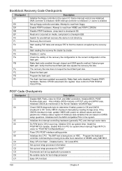
...write disabled. Restore CPUID value back into register. Initialize status register A.Initializes data variables that the found flash part size equals the recovery file size. Verify that are initialized. Program the flash part. Disable ATAPI hardware. Early CPU Init Start -- Attempt to find...enabled through chipset and OEM specific method. Also initialize BIOS modules on POST entry and GPNV area. Disable L1 cache. The recovery file size does not equal the found . Fixes CPU POST interface calling pointer. Install the POSTINT1Ch handler. Program the keyboard ...
...write disabled. Restore CPUID value back into register. Initialize status register A.Initializes data variables that the found flash part size equals the recovery file size. Verify that are initialized. Program the flash part. Disable ATAPI hardware. Early CPU Init Start -- Attempt to find...enabled through chipset and OEM specific method. Also initialize BIOS modules on POST entry and GPNV area. Disable L1 cache. The recovery file size does not equal the found . Fixes CPU POST interface calling pointer. Install the POSTINT1Ch handler. Program the keyboard ...
Service Guide
Page 182
... PnP and PCI boot devices. Initialize different buses and perform the following functions: Reset, Detect, and Disable (function 0); General Device Initialization (function 5). Function 4 searches for recovery Flash Programming successful File read /write test error Keyboard controller BAT command failed General exception error (processor exception interrupt error) Chapter 4 172 Indicates the system...
... PnP and PCI boot devices. Initialize different buses and perform the following functions: Reset, Detect, and Disable (function 0); General Device Initialization (function 5). Function 4 searches for recovery Flash Programming successful File read /write test error Keyboard controller BAT command failed General exception error (processor exception interrupt error) Chapter 4 172 Indicates the system...
Service Guide
Page 186
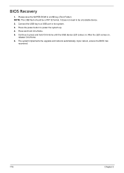
Please save the SUPER.ROM to be a FAT 32 format. NOTE: The USB flash should be a bootable device. 2. It does not need to a USB key (Root Folder). Press and hold Ctrl+Home until the USB device LED comes on , release Ctrl+Home. 6. The system implements the upgrade and reboots automatically. Connect the USB key to power the system up. 4. BIOS Recovery 1. Upon reboot, ensure the BIOS has recovered. 176 Chapter 5 Press the power button to a USB port in the system. 3. Continue to press and hold Ctrl+Home. 5. After the LED comes on .
Please save the SUPER.ROM to be a FAT 32 format. NOTE: The USB flash should be a bootable device. 2. It does not need to a USB key (Root Folder). Press and hold Ctrl+Home until the USB device LED comes on , release Ctrl+Home. 6. The system implements the upgrade and reboots automatically. Connect the USB key to power the system up. 4. BIOS Recovery 1. Upon reboot, ensure the BIOS has recovered. 176 Chapter 5 Press the power button to a USB port in the system. 3. Continue to press and hold Ctrl+Home. 5. After the LED comes on .

