Service Guide
Page 7
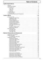
... Features 33 BIOS Flash Utilities 36 DOS Flash Utility 37 Win Flash Utility 38 Using DMI Tools 39 Machine Disassembly and Replacement 40 Disassembly Requirements 40 General Information 40 Pre-disassembly Instructions 40 Disassembly Process 42 Disassembly Flowchart 42 Removing the RAM Covers 44 Removing the RAM 46 Removing the Rear Covers 47 Removing the...
... Features 33 BIOS Flash Utilities 36 DOS Flash Utility 37 Win Flash Utility 38 Using DMI Tools 39 Machine Disassembly and Replacement 40 Disassembly Requirements 40 General Information 40 Pre-disassembly Instructions 40 Disassembly Process 42 Disassembly Flowchart 42 Removing the RAM Covers 44 Removing the RAM 46 Removing the Rear Covers 47 Removing the...
Service Guide
Page 50
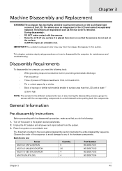
... hardware components. This chapter contains step-by-step procedures on the surface. • ALWAYS employ an antistatic mat. During the disassembly process, group the screws with the sensors. • Raise the LCD off the power to any surface it is removed. Main...tools: • Wrist grounding strap and conductive mat for the different components vary in the succeeding disassembly section illustrates the entire disassembly sequence. Disassembly Requirements To disassemble the computer, you do not rest on how to avoid mismatch when putting back the components. Place...
... hardware components. This chapter contains step-by-step procedures on the surface. • ALWAYS employ an antistatic mat. During the disassembly process, group the screws with the sensors. • Raise the LCD off the power to any surface it is removed. Main...tools: • Wrist grounding strap and conductive mat for the different components vary in the succeeding disassembly section illustrates the entire disassembly sequence. Disassembly Requirements To disassemble the computer, you do not rest on how to avoid mismatch when putting back the components. Place...
Service Guide
Page 52
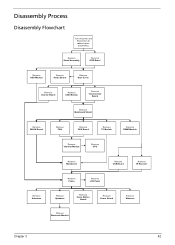
Disassembly Process Disassembly Flowchart Turn off power and disconnect all cables before proceeding Remove Stand Assembly Remove ODD Bezel Remove HDD Module Remove Audio Board Remove Rear Cover ...
Disassembly Process Disassembly Flowchart Turn off power and disconnect all cables before proceeding Remove Stand Assembly Remove ODD Bezel Remove HDD Module Remove Audio Board Remove Rear Cover ...
Service Guide
Page 54
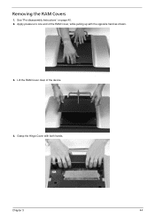
Lift the RAM Cover clear of the RAM Cover, while pulling up with both hands. Grasp the Hinge Cover with the opposite hand as shown. 3. Apply pressure to one end of the device. 4. Chapter 3 44 See "Pre-disassembly Instructions" on page 40. 2. Removing the RAM Covers 1.
Lift the RAM Cover clear of the RAM Cover, while pulling up with both hands. Grasp the Hinge Cover with the opposite hand as shown. 3. Apply pressure to one end of the device. 4. Chapter 3 44 See "Pre-disassembly Instructions" on page 40. 2. Removing the RAM Covers 1.
Service Guide
Page 104
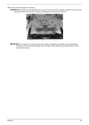
IMPORTANT:Do not place the LCD panel face down. When following the remainder of the device. WARNING:When lifting the LCD Assembly, do not touch the Touch sensor modules located at the top left and top right corners of the disassembly instructions, place something between the LCD face and the tabletop to prevent pressure on the touchscreen sensors. 15. Lift the LCD bracket clear of the bezel. Doing so will damage the touch screen function. Chapter 3 94
IMPORTANT:Do not place the LCD panel face down. When following the remainder of the device. WARNING:When lifting the LCD Assembly, do not touch the Touch sensor modules located at the top left and top right corners of the disassembly instructions, place something between the LCD face and the tabletop to prevent pressure on the touchscreen sensors. 15. Lift the LCD bracket clear of the bezel. Doing so will damage the touch screen function. Chapter 3 94
Service Guide
Page 167
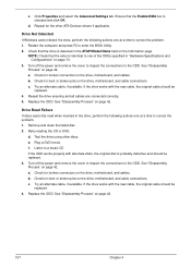
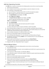
..." on page 42. Retry reading the CD or DVD. Test the drive using other ATA Devices shown if applicable. See "Disassembly Process" on page 42. See "Disassembly Process" on the drive, motherboard, and cables. a. c. Repeat for broken connectors on page 42. Restart the computer and ... ODD. d. Try an alternate cable, if available. Check for broken connectors on page 42. 157 Chapter 4 Replace the ODD. c. See "Disassembly Process" on the drive, motherboard, and cables. c. Reseat the drive ensuring and all cables are connected correctly. 5. Turn off the power and...
..." on page 42. Retry reading the CD or DVD. Test the drive using other ATA Devices shown if applicable. See "Disassembly Process" on page 42. See "Disassembly Process" on the drive, motherboard, and cables. a. c. Repeat for broken connectors on page 42. Restart the computer and ... ODD. d. Try an alternate cable, if available. Check for broken connectors on page 42. 157 Chapter 4 Replace the ODD. c. See "Disassembly Process" on the drive, motherboard, and cables. c. Reseat the drive ensuring and all cables are connected correctly. 5. Turn off the power and...
Service Guide
Page 172
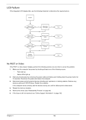
... to determine the required action: START Check LCD cable connected OK Check LCD cable is good OK Check LCD module is still not resolved, see "Disassembly Process" on page 192. Disconnect power and all external devices including port replicators or docking stations. Restart the computer. LCD Failure If the integrated LCD...
... to determine the required action: START Check LCD cable connected OK Check LCD cable is good OK Check LCD module is still not resolved, see "Disassembly Process" on page 192. Disconnect power and all external devices including port replicators or docking stations. Restart the computer. LCD Failure If the integrated LCD...
Service Guide
Page 173
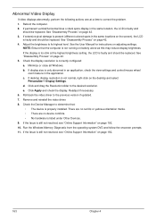
...control/mouse wheel zoom feature in the application. If the Issue is still not resolved, see "Online Support Information" on page 42. 3. See "Disassembly Process" on adjusting settings. See the User Manual for instructions on page 42. 4. b. If display size is listed under Other Devices. 9. Abnormal... Run the Windows Memory Diagnostic from the operating system DVD and follow the onscreen prompts. 11. Click Apply and check the display. See "Disassembly Process" on page 192. 10. If the Issue is still not resolved, see "Online Support Information" on battery alone as this may ...
...control/mouse wheel zoom feature in the application. If the Issue is still not resolved, see "Online Support Information" on page 42. 3. See "Disassembly Process" on adjusting settings. See the User Manual for instructions on page 42. 4. b. If display size is listed under Other Devices. 9. Abnormal... Run the Windows Memory Diagnostic from the operating system DVD and follow the onscreen prompts. 11. Click Apply and check the display. See "Disassembly Process" on page 192. 10. If the Issue is still not resolved, see "Online Support Information" on battery alone as this may ...
Service Guide
Page 175
... Next. i. Restart the computer and press F2 to locate and resolve issues with the computer. Ensure all external devices. 2. Run the Windows Disk Defragmenter. See "Disassembly Process" on page 42. If the mouse uses a USB connection, try an alternate USB port. 4. f. Select Startup Repair. If the issue is not fixed, repeat...
... Next. i. Restart the computer and press F2 to locate and resolve issues with the computer. Ensure all external devices. 2. Run the Windows Disk Defragmenter. See "Disassembly Process" on page 42. If the mouse uses a USB connection, try an alternate USB port. 4. f. Select Startup Repair. If the issue is not fixed, repeat...
Service Guide
Page 203
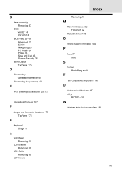
... 27 Exit 36 Navigating 23 PC Health 36 Power 36 Save and Exit 36 System Security 36 Board Layout Top View 175 D Disassembly General Information 40 Disassembly Requirements 40 F FRU (Field Replaceable Unit) List 177 I Intermittent Problems 167 J Jumper and Connector Locations 175 Top View 175... K Keyboard Usage 11 L LCD Bezel Removing 50 LCD Brackets Removing 58 LCD Cable Removing 58 LCD Module Index Removing 48 M Main Unit Disassembly Flowchart 42 Model Definition 188 O Online Support Information 192 P Panel 7 front 7 S System Block Diagram 6 T Test Compatible Components 190 U ...
... 27 Exit 36 Navigating 23 PC Health 36 Power 36 Save and Exit 36 System Security 36 Board Layout Top View 175 D Disassembly General Information 40 Disassembly Requirements 40 F FRU (Field Replaceable Unit) List 177 I Intermittent Problems 167 J Jumper and Connector Locations 175 Top View 175... K Keyboard Usage 11 L LCD Bezel Removing 50 LCD Brackets Removing 58 LCD Cable Removing 58 LCD Module Index Removing 48 M Main Unit Disassembly Flowchart 42 Model Definition 188 O Online Support Information 192 P Panel 7 front 7 S System Block Diagram 6 T Test Compatible Components 190 U ...


