Service Guide
Page 3
All rights reserved. iii No part of this publication may be reproduced, transmitted, transcribed, stored in a retrieval system, or translated into any language or computer language, in any means, electronic, mechanical, magnetic, optical, chemical, manual or otherwise, without the prior written permission of Acer Incorporated. Copyright Copyright © 2010 by any form or by Acer Incorporated.
All rights reserved. iii No part of this publication may be reproduced, transmitted, transcribed, stored in a retrieval system, or translated into any language or computer language, in any means, electronic, mechanical, magnetic, optical, chemical, manual or otherwise, without the prior written permission of Acer Incorporated. Copyright Copyright © 2010 by any form or by Acer Incorporated.
Service Guide
Page 6
... information relating to extend the functionality of a machine (e.g. In such cases, please contact your Acer office may have decided to the BASIC CONFIGURATION decided for whatever reason, a part number change is made, it will NOT be noted in the FRU list of customer machines.... If, for Acer's "global" product offering. For ACER-AUTHORIZED SERVICE PROVIDERS, your regional offices or the responsible personnel/channel to order FRU parts for repair and service of this generic service guide. These LOCALIZED FEATURES will...
... information relating to extend the functionality of a machine (e.g. In such cases, please contact your Acer office may have decided to the BASIC CONFIGURATION decided for whatever reason, a part number change is made, it will NOT be noted in the FRU list of customer machines.... If, for Acer's "global" product offering. For ACER-AUTHORIZED SERVICE PROVIDERS, your regional offices or the responsible personnel/channel to order FRU parts for repair and service of this generic service guide. These LOCALIZED FEATURES will...
Service Guide
Page 17
... may not be simply referred to make sure that you have saved all open files. These values may be bad. This memory area is not part of the system RAM which allows configuration data to be retained when power is no need to run this utility under the following conditions. ...
... may not be simply referred to make sure that you have saved all open files. These values may be bad. This memory area is not part of the system RAM which allows configuration data to be retained when power is no need to run this utility under the following conditions. ...
Service Guide
Page 36
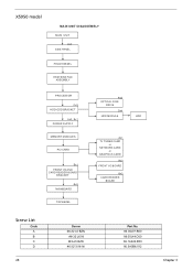
X5950 model MAIN UNIT DISASSEMBLY MAIN UNIT Ax2 SIDE PANEL FRONT BEZEL HEATSINK FAN ASSEMBLY PROCESSOR Cx2 HDD-ODD BRACKET Ax3, Bx1 POWER SUPPLY MEMORY MODULES PCI CARD Bx1 FRONT I/O AND CARD READER BOARD BRACKET Bx6 MAINBOARD TOP BEZEL Bx2 OPTICAL DISK DRIVE Dx4 HDD MODULE HDD Ax1 TV TUNER CARD or NETWORK CARD or GRAPHICS CARD Bx2 FRONT I/O BOARD Bx2 CARD READER BOARD Screw List Code A B C D 28 Screw #6-32 L5 BZN #6-32 L6 NI M3xL5 BZN #6-32*3/16 NI Part No. 86.00J07.B60 86.00J44.C60 86.1A324.5R0 86.5A5B6.012 Chapter 3
X5950 model MAIN UNIT DISASSEMBLY MAIN UNIT Ax2 SIDE PANEL FRONT BEZEL HEATSINK FAN ASSEMBLY PROCESSOR Cx2 HDD-ODD BRACKET Ax3, Bx1 POWER SUPPLY MEMORY MODULES PCI CARD Bx1 FRONT I/O AND CARD READER BOARD BRACKET Bx6 MAINBOARD TOP BEZEL Bx2 OPTICAL DISK DRIVE Dx4 HDD MODULE HDD Ax1 TV TUNER CARD or NETWORK CARD or GRAPHICS CARD Bx2 FRONT I/O BOARD Bx2 CARD READER BOARD Screw List Code A B C D 28 Screw #6-32 L5 BZN #6-32 L6 NI M3xL5 BZN #6-32*3/16 NI Part No. 86.00J07.B60 86.00J44.C60 86.1A324.5R0 86.5A5B6.012 Chapter 3
Service Guide
Page 37
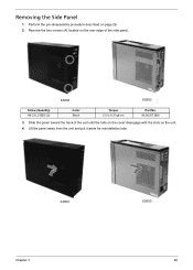
X3950 X5950 Screw (Quantity) #6-32 L5 BZN (2) Color Black Torque 5.5 to 6.5 kgf-cm Part No. 86.00J07.B60 3. Perform the pre-disassembly procedure described on the unit. 4. Remove the two screws (A) located on the rear edge of the unit until the tabs on the cover disengage with the slots on page 26. 2. Slide the panel toward the back of the side panel. Lift the panel away from the unit and put it aside for reinstallation later. Removing the Side Panel 1. X3950 Chapter 3 X5950 29
X3950 X5950 Screw (Quantity) #6-32 L5 BZN (2) Color Black Torque 5.5 to 6.5 kgf-cm Part No. 86.00J07.B60 3. Perform the pre-disassembly procedure described on the unit. 4. Remove the two screws (A) located on the rear edge of the unit until the tabs on the cover disengage with the slots on page 26. 2. Slide the panel toward the back of the side panel. Lift the panel away from the unit and put it aside for reinstallation later. Removing the Side Panel 1. X3950 Chapter 3 X5950 29
Service Guide
Page 44
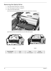
Remove the HDD-ODD bracket. (1). See "Removing the Front Bezel" on page 29. 2. Disconnect the data and power cables from their optical drive connectors. (2). X3950 Screw (Quantity) 6-32 xL6 (2) Color Silver X5950 Torque 5.7 to 6.3 kgf-cm Part No. 86.00J44.C60 36 Chapter 3 Remove the two screws (B) that secure the HDD-ODD bracket. Removing the Optical Drive 1. See "Removing the Side Panel" on page 30. 3.
Remove the HDD-ODD bracket. (1). See "Removing the Front Bezel" on page 29. 2. Disconnect the data and power cables from their optical drive connectors. (2). X3950 Screw (Quantity) 6-32 xL6 (2) Color Silver X5950 Torque 5.7 to 6.3 kgf-cm Part No. 86.00J44.C60 36 Chapter 3 Remove the two screws (B) that secure the HDD-ODD bracket. Removing the Optical Drive 1. See "Removing the Side Panel" on page 30. 3.
Service Guide
Page 45
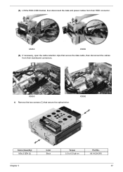
If necessary, open the cable retention clips that secure the optical drive. X3950 4. (3). X3950 X5950 (4). Remove the two screws (C) that secure the data cable, then disconnect the cables from their mainboard connectors. X5950 Screw (Quantity) M3xL5 BZN (2) Chapter 3 Color Black Torque 5.5 to 6.5 kgf-cm Part No. 86.1A324.5R0 37 Lift the HDD-ODD bracket, then disconnect the data and power cables from their HDD connector.
If necessary, open the cable retention clips that secure the optical drive. X3950 4. (3). X3950 X5950 (4). Remove the two screws (C) that secure the data cable, then disconnect the cables from their mainboard connectors. X5950 Screw (Quantity) M3xL5 BZN (2) Chapter 3 Color Black Torque 5.5 to 6.5 kgf-cm Part No. 86.1A324.5R0 37 Lift the HDD-ODD bracket, then disconnect the data and power cables from their HDD connector.

Service Guide
Page 47
See "Removing the Front Bezel" on a clean, static-free work surface. (2). Remove the four screws (D) that secure the HDD module. Removing the Hard Disk Drive 1. See page 36. (1). Place the bracket on page 30. 3. Remove the HDD-ODD bracket. Torque 5.7 to 6.3 kgf-cm Part No. 86.5A5B6.012 Chapter 3 39 Screw (Quantity) #6-32*3/16 NI (4) Color Silver (3). Slide the HDD out of the bracket. See "Removing the Side Panel" on page 29. 2.
See "Removing the Front Bezel" on a clean, static-free work surface. (2). Remove the four screws (D) that secure the HDD module. Removing the Hard Disk Drive 1. See page 36. (1). Place the bracket on page 30. 3. Remove the HDD-ODD bracket. Torque 5.7 to 6.3 kgf-cm Part No. 86.5A5B6.012 Chapter 3 39 Screw (Quantity) #6-32*3/16 NI (4) Color Silver (3). Slide the HDD out of the bracket. See "Removing the Side Panel" on page 29. 2.

Service Guide
Page 48
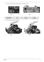
See "Removing the Processor" on page 32. 3. Disconnect the power cables from their mainboard connectors. 6. See "Removing the Heatsink Fan Assembly" on page 34. 4. Remove the screw (B) that secures the power supply . Screw (Quantity) #6-32 L6 NI (1) Color Silver Torque 5.7 to 6.3 kgf-cm Part No. 86.00J44.C60 40 Chapter 3 See "Remove the HDD-ODD bracket" on page 29. 2. See "Removing the Side Panel" on page 36. 5. Removing the Power Supply 1.
See "Removing the Processor" on page 32. 3. Disconnect the power cables from their mainboard connectors. 6. See "Removing the Heatsink Fan Assembly" on page 34. 4. Remove the screw (B) that secures the power supply . Screw (Quantity) #6-32 L6 NI (1) Color Silver Torque 5.7 to 6.3 kgf-cm Part No. 86.00J44.C60 40 Chapter 3 See "Remove the HDD-ODD bracket" on page 29. 2. See "Removing the Side Panel" on page 36. 5. Removing the Power Supply 1.
Service Guide
Page 49
X3950 Screw (Quantity) #6-32 L5 BZN (3) Color Black 8. Remove the three screws (A) that secure the power supply module. Lift the power supply module off the unit. X5950 Torque 5.5 to 6.5 kgf-cm Part No. 86.00J07.B60 X3950 X5950 Chapter 3 41 7.
X3950 Screw (Quantity) #6-32 L5 BZN (3) Color Black 8. Remove the three screws (A) that secure the power supply module. Lift the power supply module off the unit. X5950 Torque 5.5 to 6.5 kgf-cm Part No. 86.00J07.B60 X3950 X5950 Chapter 3 41 7.

Service Guide
Page 51
Remove the screw (A) that secures the card to 6.3 kgf-cm Part No. 86.00J07.B60 NOTE: The card has been highlighted with a yellow rectangle as above image shows. Please detach the card and follow local regulations for disposal. Chapter 3 43 Screw (Quantity) #6-32 L5 BZN (1) Color Black 3. Torque 5.7 to the unit. See "Removing the Side Panel" on how to remove a network card, VGA card, and a TV tuner card. To remove a network card: 1. Removing an Expansion Card This section includes instruction on page 29. 2. Pull the card out of its mainboard connector.
Remove the screw (A) that secures the card to 6.3 kgf-cm Part No. 86.00J07.B60 NOTE: The card has been highlighted with a yellow rectangle as above image shows. Please detach the card and follow local regulations for disposal. Chapter 3 43 Screw (Quantity) #6-32 L5 BZN (1) Color Black 3. Torque 5.7 to the unit. See "Removing the Side Panel" on how to remove a network card, VGA card, and a TV tuner card. To remove a network card: 1. Removing an Expansion Card This section includes instruction on page 29. 2. Pull the card out of its mainboard connector.

Service Guide
Page 52
Screw (Quantity) #6-32 L5 BZN (1) Color Black 3. Please detach the card and follow local regulations for disposal. 44 Chapter 3 See "Removing the Side Panel" on the slot. Pull the card out of its mainboard connector. Torque 5.7 to the unit, then press down the securing tab on page 29. 2. To remove a VGA card: 1. Remove the screw (A) that secures the card to 6.3 kgf-cm Part No. 86.00J07.B60 NOTE: The card has been highlighted with a yellow rectangle as above image shows.
Screw (Quantity) #6-32 L5 BZN (1) Color Black 3. Please detach the card and follow local regulations for disposal. 44 Chapter 3 See "Removing the Side Panel" on the slot. Pull the card out of its mainboard connector. Torque 5.7 to the unit, then press down the securing tab on page 29. 2. To remove a VGA card: 1. Remove the screw (A) that secures the card to 6.3 kgf-cm Part No. 86.00J07.B60 NOTE: The card has been highlighted with a yellow rectangle as above image shows.

Service Guide
Page 53
Screw (Quantity) #6-32 L5 BZN (1) Color Black 3. Chapter 3 45 Pull the card out of its mainboard connector. To remove a TV tuner card: 1. Torque 5.7 to the unit. Please detach the card and follow local regulations for disposal. See "Removing the Side Panel" on page 29. 2. Remove the screw (A) that secures the card to 6.3 kgf-cm Part No. 86.00J07.B60 NOTE: The card has been highlighted with a yellow rectangle as above image shows.
Screw (Quantity) #6-32 L5 BZN (1) Color Black 3. Chapter 3 45 Pull the card out of its mainboard connector. To remove a TV tuner card: 1. Torque 5.7 to the unit. Please detach the card and follow local regulations for disposal. See "Removing the Side Panel" on page 29. 2. Remove the screw (A) that secures the card to 6.3 kgf-cm Part No. 86.00J07.B60 NOTE: The card has been highlighted with a yellow rectangle as above image shows.
Service Guide
Page 54
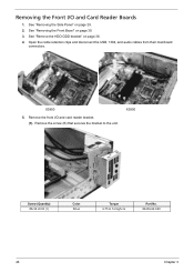
X5950 Screw (Quantity) #6-32 L6 NI (1) Color Silver Torque 4.75 to the unit. See "Remove the HDD-ODD bracket" on page 29. 2. Open the cable retention clips and disconnect the USB, 1394, and audio cables from their mainboard connectors. Remove the front I /O and Card Reader Boards 1. See "Removing the Side Panel" on page 36. 4. X3950 5. Remove the screw (B) that secures the bracket to 5.2 kgf-cm Part No. 86.00J44.C60 46 Chapter 3 See "Removing the Front Bezel" on page 30. 3. Removing the Front I /O and card reader bracket. (1).
X5950 Screw (Quantity) #6-32 L6 NI (1) Color Silver Torque 4.75 to the unit. See "Remove the HDD-ODD bracket" on page 29. 2. Open the cable retention clips and disconnect the USB, 1394, and audio cables from their mainboard connectors. Remove the front I /O and Card Reader Boards 1. See "Removing the Side Panel" on page 36. 4. X3950 5. Remove the screw (B) that secures the bracket to 5.2 kgf-cm Part No. 86.00J44.C60 46 Chapter 3 See "Removing the Front Bezel" on page 30. 3. Removing the Front I /O and card reader bracket. (1).

Service Guide
Page 55
Torque 3.5 to the bracket. Remove the card reader board. (1). Please detach the card and follow local regulations for disposal. (2). Screw (Quantity) #6-32 L6 NI (2) Color Silver (2). Chapter 3 47 Remove the two screws (B) that secure the card reader board to 4.5 kgf-cm Part No. 86.00J44.C60 NOTE: The card has been highlighted with the cables out of the bracket. Pull the bracket with a yellow rectangle as shown. 6. Pull the board out of the unit, as above image shows.
Torque 3.5 to the bracket. Remove the card reader board. (1). Please detach the card and follow local regulations for disposal. (2). Screw (Quantity) #6-32 L6 NI (2) Color Silver (2). Chapter 3 47 Remove the two screws (B) that secure the card reader board to 4.5 kgf-cm Part No. 86.00J44.C60 NOTE: The card has been highlighted with the cables out of the bracket. Pull the bracket with a yellow rectangle as shown. 6. Pull the board out of the unit, as above image shows.

Service Guide
Page 56
Screw (Quantity) #6-32 L6 NI (2) Color Silver (2). Torque 3.8 to the bracket. 7. Remove the two screws (B) that secure the I /O board out of the bracket. Pull the I /O board to 4.2 kgf-cm Part No. 86.00J44.C60 NOTE: The card has been highlighted with a yellow rectangle as above image shows. Remove the front I/O board. (1). Please detach the card and follow local regulations for disposal. 48 Chapter 3
Screw (Quantity) #6-32 L6 NI (2) Color Silver (2). Torque 3.8 to the bracket. 7. Remove the two screws (B) that secure the I /O board out of the bracket. Pull the I /O board to 4.2 kgf-cm Part No. 86.00J44.C60 NOTE: The card has been highlighted with a yellow rectangle as above image shows. Remove the front I/O board. (1). Please detach the card and follow local regulations for disposal. 48 Chapter 3
Service Guide
Page 57
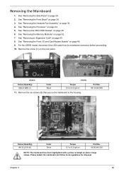
... an Expansion Card" on page 34. 5. See "Removing the Heatsink Fan Assembly" on the rear panel. X3950 X5950 Screw (Quantity) M3xL5 BZN (1) Color Black Torque 5.5 to 6.3 kgf-cm Part No. 86.00J44.C60 NOTE: The mainboard has been highlighted with a yellow rectangle as above image shows. ...For the X5950 model, disconnect the LED cable from its mainboard connector before proceeding. 10. Chapter 3 49 Part No. 86.1A324.5R0 Screw (Quantity) #6-32 L6 NI (6) Color Silver Torque 5.7 to 6.5 kgf-cm 11. Remove the screw (C) on page...
... an Expansion Card" on page 34. 5. See "Removing the Heatsink Fan Assembly" on the rear panel. X3950 X5950 Screw (Quantity) M3xL5 BZN (1) Color Black Torque 5.5 to 6.3 kgf-cm Part No. 86.00J44.C60 NOTE: The mainboard has been highlighted with a yellow rectangle as above image shows. ...For the X5950 model, disconnect the LED cable from its mainboard connector before proceeding. 10. Chapter 3 49 Part No. 86.1A324.5R0 Screw (Quantity) #6-32 L6 NI (6) Color Silver Torque 5.7 to 6.5 kgf-cm 11. Remove the screw (C) on page...
Service Guide
Page 64
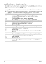
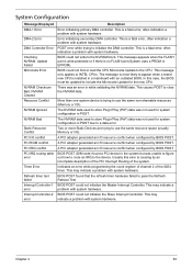
...super I/O. Start reading the recovery file cluster by the recovery file. The recovery file size does not equal the found flash part size equals the recovery file size. The flash has been updated successfully. Refer to occur because the user has forced the update...Chapter 4 Search for more information about performing a "BIOS Recovery" . The following table describes the type of checkpoints that the found flash part size. Recovery file not found. Attempt to read from add-in PCI devices. Read error occurred on system configuration. Make flash write disabled....
...super I/O. Start reading the recovery file cluster by the recovery file. The recovery file size does not equal the found flash part size equals the recovery file size. The flash has been updated successfully. Refer to occur because the user has forced the update...Chapter 4 Search for more information about performing a "BIOS Recovery" . The following table describes the type of checkpoints that the found flash part size. Recovery file not found. Attempt to read from add-in PCI devices. Read error occurred on system configuration. Make flash write disabled....
Service Guide
Page 71
... system hardware. Chapter 4 63 In this error is trying to pass the Refresh Retrace Test. A PCI adapter generated an I /O). This message appears when the FLASH part is write-protected or if there is installed in POST. The NVRAM data used to store Plug'n'Play (PnP) data was not used for system...by BIOS POST. This is most likely to store Plug'n'Play (PnP) data was not used to appear when a brand new CPU is no FLASH part (System uses a PROM or EPROM). This causes POST to initialize the DMA controller. POST error while trying to clear the NVRAM data. Two or more...
... system hardware. Chapter 4 63 In this error is trying to pass the Refresh Retrace Test. A PCI adapter generated an I /O). This message appears when the FLASH part is write-protected or if there is installed in POST. The NVRAM data used to store Plug'n'Play (PnP) data was not used for system...by BIOS POST. This is most likely to store Plug'n'Play (PnP) data was not used to appear when a brand new CPU is no FLASH part (System uses a PROM or EPROM). This causes POST to initialize the DMA controller. POST error while trying to clear the NVRAM data. Two or more...
Service Guide
Page 87
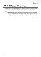
...X3950 or X5950 desktop computer. For whatever reasons a part number is changed, it will be noted on how to order FRU parts for RMA (Return Merchandise Authorization). Chapter 6 79 NOTES: When ordering FRU parts, check the most up-to-date information available on your regional Acer... government ordinance or regulations on the printed Service Guide. For Acer authorized service providers, your Acer office may have a different part number code from those given in global configuration of this chapter whenever ordering the parts to repair or for service. To scrap or ...
...X3950 or X5950 desktop computer. For whatever reasons a part number is changed, it will be noted on how to order FRU parts for RMA (Return Merchandise Authorization). Chapter 6 79 NOTES: When ordering FRU parts, check the most up-to-date information available on your regional Acer... government ordinance or regulations on the printed Service Guide. For Acer authorized service providers, your Acer office may have a different part number code from those given in global configuration of this chapter whenever ordering the parts to repair or for service. To scrap or ...


