
Service Guide
Page 7
... Processor 33 Removing the Optical Drive 34 Removing the Hard Disk Drive 37 Removing the Power Supply 38 Removing the Memory Modules 40 Removing the TV Tuner Card 41 Removing the VGA Card 42 Removing the Front I/O and Card Reader Boards 43 Removing the Mainboard 46 Hardware Diagnostic Procedure 49 Chapter 4 System...
... Processor 33 Removing the Optical Drive 34 Removing the Hard Disk Drive 37 Removing the Power Supply 38 Removing the Memory Modules 40 Removing the TV Tuner Card 41 Removing the VGA Card 42 Removing the Front I/O and Card Reader Boards 43 Removing the Mainboard 46 Hardware Diagnostic Procedure 49 Chapter 4 System...
Service Guide
Page 14
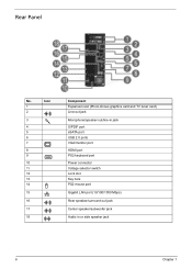
Rear Panel No. Icon 1 2 3 4 5 6 7 8 9 10 11 12 13 14 15 16 17 18 Component Expansion slot (Photo shows graphics card and TV tuner card) Line-out jack Microphone/speaker-out/line-in jack S/PDIF port eSATA port USB 2.0 ports VGA/monitor port HDMI port PS2 keyboard port Power connector Voltage selector switch Lock slot Key hole PS2 mouse port Gigabit LAN port (10/100/1000 Mbps) Rear speaker/surround out jack Center speaker/subwoofer jack Audio in or side speaker jack 6 Chapter 1
Rear Panel No. Icon 1 2 3 4 5 6 7 8 9 10 11 12 13 14 15 16 17 18 Component Expansion slot (Photo shows graphics card and TV tuner card) Line-out jack Microphone/speaker-out/line-in jack S/PDIF port eSATA port USB 2.0 ports VGA/monitor port HDMI port PS2 keyboard port Power connector Voltage selector switch Lock slot Key hole PS2 mouse port Gigabit LAN port (10/100/1000 Mbps) Rear speaker/surround out jack Center speaker/subwoofer jack Audio in or side speaker jack 6 Chapter 1

Service Guide
Page 37
Main Unit Disassembly MAIN UNIT DISASSEMBLY MAIN UNIT Ax2 SIDE PANEL FRONT BEZEL HEAT SINK FAN ASSEMBLY Bx2 OPTICAL DRIVE CPU Bx2 HDD-ODD BRACKET Ax3, Bx1 POWER SUPPLY Cx4 HDD MODULE HDD MEMORY MODULES Ax1 TV TUNER CARD Ax1 VGA CARD Bx1 FRONT I/O AND CARD READER BOARD BRACKET Bx6, Dx1 MAINBOARD Bx2 FRONT I/O BOARD Bx2 CARD READER BOARD Screw List A B C D Screw #6-32 L5 BZN #6-32 L6 NI #6-32*3/16 NI M3xL5 BZN Part No. 86.00J07.B60 86.00J44.C60 86.1A324.5R0 86.5A5B6.012 Chapter 3 29
Main Unit Disassembly MAIN UNIT DISASSEMBLY MAIN UNIT Ax2 SIDE PANEL FRONT BEZEL HEAT SINK FAN ASSEMBLY Bx2 OPTICAL DRIVE CPU Bx2 HDD-ODD BRACKET Ax3, Bx1 POWER SUPPLY Cx4 HDD MODULE HDD MEMORY MODULES Ax1 TV TUNER CARD Ax1 VGA CARD Bx1 FRONT I/O AND CARD READER BOARD BRACKET Bx6, Dx1 MAINBOARD Bx2 FRONT I/O BOARD Bx2 CARD READER BOARD Screw List A B C D Screw #6-32 L5 BZN #6-32 L6 NI #6-32*3/16 NI M3xL5 BZN Part No. 86.00J07.B60 86.00J44.C60 86.1A324.5R0 86.5A5B6.012 Chapter 3 29

Service Guide
Page 49
Screw (Quantity) #6-32 L5 BZN (1) Color Black Torque 5.5 to remove it from the mainboard. Chapter 3 41 See "Removing the Side Panel" on page 30. 2. Part No. 86.00J07.B60 NOTE: The card has been highlighted with a yellow box as above image shows. Please detach the card and follow local regulations for disposal. Gently pull the card to 6.5 kgf-cm 3. Remove the screw (A) that secures the card to the chassis. Removing the TV Tuner Card 1.
Screw (Quantity) #6-32 L5 BZN (1) Color Black Torque 5.5 to remove it from the mainboard. Chapter 3 41 See "Removing the Side Panel" on page 30. 2. Part No. 86.00J07.B60 NOTE: The card has been highlighted with a yellow box as above image shows. Please detach the card and follow local regulations for disposal. Gently pull the card to 6.5 kgf-cm 3. Remove the screw (A) that secures the card to the chassis. Removing the TV Tuner Card 1.

Service Guide
Page 54
... Drive" on page 41. 9. Remove the six screws (B) that secure the mainboard to 6.3 kgf-cm Part No. 86.00J44.C60 46 Chapter 3 See "Removing the TV Tuner Card" on page 37. 7. Screw (Quantity) #6-32 L6 (6) Color Silver Torque 5.7 to the chassis.
... Drive" on page 41. 9. Remove the six screws (B) that secure the mainboard to 6.3 kgf-cm Part No. 86.00J44.C60 46 Chapter 3 See "Removing the TV Tuner Card" on page 37. 7. Screw (Quantity) #6-32 L6 (6) Color Silver Torque 5.7 to the chassis.


