Service Guide
Page 7
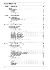
...Heat Sink Fan Assembly 32 Removing the Processor 33 Removing the Optical Drive 34 Removing the Hard Disk Drive 37 Removing the Power Supply 38 Removing the Memory Modules 40 Removing the TV Tuner Card 41 Removing the VGA Card 42 Removing the Front I/O... and Card Reader Boards 44 Removing the Mainboard 47 Hardware Diagnostic Procedure 49 Chapter 4 System Troubleshooting 49 System Check Procedures 50 Power System Check 50 System External Inspection 50 System Internal Inspection 50 Checkpoints 51 Viewing BIOS checkpoints 51 Bootblock Initialization Code Checkpoints 51 Bootblock...
...Heat Sink Fan Assembly 32 Removing the Processor 33 Removing the Optical Drive 34 Removing the Hard Disk Drive 37 Removing the Power Supply 38 Removing the Memory Modules 40 Removing the TV Tuner Card 41 Removing the VGA Card 42 Removing the Front I/O... and Card Reader Boards 44 Removing the Mainboard 47 Hardware Diagnostic Procedure 49 Chapter 4 System Troubleshooting 49 System Check Procedures 50 Power System Check 50 System External Inspection 50 System Internal Inspection 50 Checkpoints 51 Viewing BIOS checkpoints 51 Bootblock Initialization Code Checkpoints 51 Bootblock...
Service Guide
Page 10
...; Operating system options: • Genuine Windows Vista® Ultimate (32/64-bit) • Genuine Windows Vista Home Premium (32/64-bit) • Applications • Acer Empowering Technology (Acer eRecovery Management) • Acer Arcade Live • McAfee Internet Security Suite 2008 Trial version • NTI MediaMaker System BIOS • SPI Flash ROM 16 MB...
...; Operating system options: • Genuine Windows Vista® Ultimate (32/64-bit) • Genuine Windows Vista Home Premium (32/64-bit) • Applications • Acer Empowering Technology (Acer eRecovery Management) • Acer Arcade Live • McAfee Internet Security Suite 2008 Trial version • NTI MediaMaker System BIOS • SPI Flash ROM 16 MB...
Service Guide
Page 12
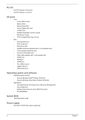
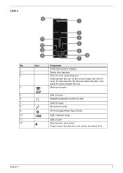
System Components This section is a virtual tour of the system's interior and exterior components. Front Panel X3812 No. Icon Component 1 HDD activity indicator 2 Optical drive bay door 3 Drive bay door eject button Press to open drive bay door and access the optical drive. 4 Media card reader 5 USB 2.0 ports 6 Headphone/Speaker-out/line-out jack 7 Front I/O cover 8 Microphone-in jack 9 CF I/II (CompactFlash Type I/II) slot 10 IEEE 1394 port (4-pin) 11 USB 2.0 port 12 Power button/power indicator 4 Chapter 1
System Components This section is a virtual tour of the system's interior and exterior components. Front Panel X3812 No. Icon Component 1 HDD activity indicator 2 Optical drive bay door 3 Drive bay door eject button Press to open drive bay door and access the optical drive. 4 Media card reader 5 USB 2.0 ports 6 Headphone/Speaker-out/line-out jack 7 Front I/O cover 8 Microphone-in jack 9 CF I/II (CompactFlash Type I/II) slot 10 IEEE 1394 port (4-pin) 11 USB 2.0 port 12 Power button/power indicator 4 Chapter 1
Service Guide
Page 13
Icon Component 1 Power button/power indicator 2 Optical drive bay door 3 Front I /O cover. Chapter 1 5 X5812 No. To close the door, flip the cover back into place, then press the cover, beneath ...
Icon Component 1 Power button/power indicator 2 Optical drive bay door 3 Front I /O cover. Chapter 1 5 X5812 No. To close the door, flip the cover back into place, then press the cover, beneath ...

Service Guide
Page 14
Icon 1 2 3 4 5 6 7 8 9 10 11 12 13 14 15 16 17 18 Component Expansion slot (Photo shows graphics card and TV tuner card) Line-out jack Microphone/speaker-out/line-in jack S/PDIF port eSATA port USB 2.0 ports VGA monitor port HDMI port PS2 keyboard port Power connector Voltage selector switch Lock slot Key hole PS2 mouse port Gigabit LAN port (10/100/1000 Mbps) Rear speaker/surround out jack Center speaker/subwoofer jack Audio in or side speaker jack 6 Chapter 1 Rear Panel No.
Icon 1 2 3 4 5 6 7 8 9 10 11 12 13 14 15 16 17 18 Component Expansion slot (Photo shows graphics card and TV tuner card) Line-out jack Microphone/speaker-out/line-in jack S/PDIF port eSATA port USB 2.0 ports VGA monitor port HDMI port PS2 keyboard port Power connector Voltage selector switch Lock slot Key hole PS2 mouse port Gigabit LAN port (10/100/1000 Mbps) Rear speaker/surround out jack Center speaker/subwoofer jack Audio in or side speaker jack 6 Chapter 1 Rear Panel No.

Service Guide
Page 15
Internal Components No. Component 1 HDD drive 2 Optical drive 3 Expansion cards 4 Mainboard 5 Heat sink fan assembly 6 Power supply Chapter 1 7
Internal Components No. Component 1 HDD drive 2 Optical drive 3 Expansion cards 4 Mainboard 5 Heat sink fan assembly 6 Power supply Chapter 1 7
Service Guide
Page 16
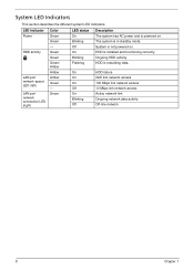
... LED Indicators This section describes the different system LED indicators. Green Green Green/ Amber Amber Amber Green - LED indicator Power Color Green LED status On Description The system has AC power and is not powered on . HDD activity LAN port network speed LED (left) LAN port network connection LED (right) Green - HDD is...
... LED Indicators This section describes the different system LED indicators. Green Green Green/ Amber Amber Amber Green - LED indicator Power Color Green LED status On Description The system has AC power and is not powered on . HDD activity LAN port network speed LED (left) LAN port network connection LED (right) Green - HDD is...
Service Guide
Page 17
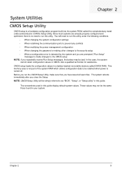
... • When changing the system configuration settings • When redefining the communication ports to prevent any conflicts • When modifying the power management configuration • When changing the password or making other changes to the security setup • When a configuration error is detected by...have saved all open files. The system reboots immediately after you repeatedly receive Run Setup messages, the battery may not be retained when power is turned off. NOTE: CMOS Setup Utility will need to be the same those found in CMOS. Chapter 2 9 The screenshots ...
... • When changing the system configuration settings • When redefining the communication ports to prevent any conflicts • When modifying the power management configuration • When changing the password or making other changes to the security setup • When a configuration error is detected by...have saved all open files. The system reboots immediately after you repeatedly receive Run Setup messages, the battery may not be retained when power is turned off. NOTE: CMOS Setup Utility will need to be the same those found in CMOS. Chapter 2 9 The screenshots ...
Service Guide
Page 19
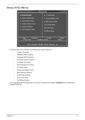
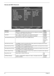
Setup Utility Menus The Setup Main menu includes the following main setup categories. • Product Information • Standard CMOS Features • Advanced BIOS Features • Advanced Chipset Features • Integrated Peripherals • Power Management Setup • PC Health Status • Frequency/Voltage Control • BIOS Security Features • Load Default Settings • Save & Exit Setup • Exit Without Saving In the descriptive table following each of the menu screenshots, settings in boldface are the default and suggested settings. Chapter 2 11
Setup Utility Menus The Setup Main menu includes the following main setup categories. • Product Information • Standard CMOS Features • Advanced BIOS Features • Advanced Chipset Features • Integrated Peripherals • Power Management Setup • PC Health Status • Frequency/Voltage Control • BIOS Security Features • Load Default Settings • Save & Exit Setup • Exit Without Saving In the descriptive table following each of the menu screenshots, settings in boldface are the default and suggested settings. Chapter 2 11
Service Guide
Page 22
... CD/DVD drives. Press Enter to access the Optical Disk Drive Priority submenu and specify the boot device priority sequence from available network devices. Selects power on state for Num Lock. Press Enter to access the Hard Disk Drive Priority submenu and specify the boot device priority sequence from available removable...
... CD/DVD drives. Press Enter to access the Optical Disk Drive Priority submenu and specify the boot device priority sequence from available network devices. Selects power on state for Num Lock. Press Enter to access the Hard Disk Drive Priority submenu and specify the boot device priority sequence from available removable...

Service Guide
Page 23
... insert a code in the buffer preventing damage and worm propagation. Enables or disables the Virtualization Technology (VT) availability. Note: A full reset is required to reduce power consumption. Select the amout of overlapped PCI memory above the total physical memory. When disabled, the system operates at maximum CPU speed. Select a video memory...
... insert a code in the buffer preventing damage and worm propagation. Enables or disables the Virtualization Technology (VT) availability. Note: A full reset is required to reduce power consumption. Select the amout of overlapped PCI memory above the total physical memory. When disabled, the system operates at maximum CPU speed. Select a video memory...

Service Guide
Page 25
... Enabled Disabled Enabled Enabled Disabled Enabled Disabled Power Off Power On Last State Chapter 2 17 Restore On AC Power Loss Enables or disables the system to wake up the system from a power saving mode using a USB keyboard or mouse. Power On by RTC Alarm Enables or disables real...or disables to wake up the system from a power saving mode using a PS2 keyboard or mouse. Power Management Setup Parameter ACPI Aware O/S ACPI Suspend Mode Description Enables or disables the Advanced Configuration and Power Management (ACPI) function. Power On by PS/2 KB/Mouse Enables or disables ...
... Enabled Disabled Enabled Enabled Disabled Enabled Disabled Power Off Power On Last State Chapter 2 17 Restore On AC Power Loss Enables or disables the system to wake up the system from a power saving mode using a USB keyboard or mouse. Power On by RTC Alarm Enables or disables real...or disables to wake up the system from a power saving mode using a PS2 keyboard or mouse. Power Management Setup Parameter ACPI Aware O/S ACPI Suspend Mode Description Enables or disables the Advanced Configuration and Power Management (ACPI) function. Power On by PS/2 KB/Mouse Enables or disables ...
Service Guide
Page 33
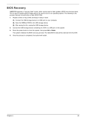
... is used to flash update a BIOS from the DOK. 4. Prepare a Disk on your computer. (2). After saving the file, unplug the USB storage device. 2. Press the power button to the USB storage device. (3). The following is completed, the system will be used to update a BIOS image without the need to boot to...
... is used to flash update a BIOS from the DOK. 4. Prepare a Disk on your computer. (2). After saving the file, unplug the USB storage device. 2. Press the power button to the USB storage device. (3). The following is completed, the system will be used to update a BIOS image without the need to boot to...
Service Guide
Page 36
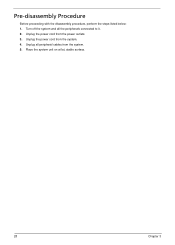
Pre-disassembly Procedure Before proceeding with the disassembly procedure, perform the steps listed below: 1. Place the system unit on a flat, stable surface. 28 Chapter 3 Unplug all the peripherals connected to it. 2. Unplug the power cord from the system. 5. Turn off the system and all peripheral cables from the power outlets. 3. Unplug the power cord from the system. 4.
Pre-disassembly Procedure Before proceeding with the disassembly procedure, perform the steps listed below: 1. Place the system unit on a flat, stable surface. 28 Chapter 3 Unplug all the peripherals connected to it. 2. Unplug the power cord from the system. 5. Turn off the system and all peripheral cables from the power outlets. 3. Unplug the power cord from the system. 4.

Service Guide
Page 37
Main Unit Disassembly MAIN UNIT DISASSEMBLY MAIN UNIT Ax2 SIDE PANEL FRONT BEZEL HEAT SINK FAN ASSEMBLY Bx2 OPTICAL DRIVE CPU Bx2 HDD-ODD BRACKET Ax3, Dx1 POWER SUPPLY Cx4 HDD MODULE HDD MEMORY MODULES Ax1 TV TUNER CARD Ax1 VGA CARD Dx1 FRONT I/O AND CARD READER BOARD BRACKET Dx6 MAINBOARD Dx2 FRONT I/O BOARD Dx2 CARD READER BOARD Screw List A B C D Screw #6-32 L5 BZN M3xL5 BZN #6-32*3/16 NI #6-32 L6 NI Part No. 86.00J07.B60 86.1A324.5R0 86.5A5B6.012 86.00J44.C60 Chapter 3 29
Main Unit Disassembly MAIN UNIT DISASSEMBLY MAIN UNIT Ax2 SIDE PANEL FRONT BEZEL HEAT SINK FAN ASSEMBLY Bx2 OPTICAL DRIVE CPU Bx2 HDD-ODD BRACKET Ax3, Dx1 POWER SUPPLY Cx4 HDD MODULE HDD MEMORY MODULES Ax1 TV TUNER CARD Ax1 VGA CARD Dx1 FRONT I/O AND CARD READER BOARD BRACKET Dx6 MAINBOARD Dx2 FRONT I/O BOARD Dx2 CARD READER BOARD Screw List A B C D Screw #6-32 L5 BZN M3xL5 BZN #6-32*3/16 NI #6-32 L6 NI Part No. 86.00J07.B60 86.1A324.5R0 86.5A5B6.012 86.00J44.C60 Chapter 3 29
Service Guide
Page 42
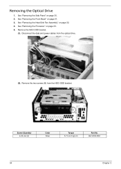
See "Removing the Processor" on page 31. 3. Screw (Quantity) 6-32 xL6 (2) Color Silver Torque 5.7 to 6.3 kgf-cm Part No. 86.1A324.5R0 34 Chapter 3 See "Removing the Front Bezel" on page 33. 5. Disconnect the data and power cables from the HDD-ODD bracket. Remove the two screws (B) from the optical drive. (2). See "Removing the Heat Sink Fan Assembly" on page 30. 2. Removing the Optical Drive 1. See "Removing the Side Panel" on page 32. 4. Remove the HDD-ODD bracket. (1).
See "Removing the Processor" on page 31. 3. Screw (Quantity) 6-32 xL6 (2) Color Silver Torque 5.7 to 6.3 kgf-cm Part No. 86.1A324.5R0 34 Chapter 3 See "Removing the Front Bezel" on page 33. 5. Disconnect the data and power cables from the HDD-ODD bracket. Remove the two screws (B) from the optical drive. (2). See "Removing the Heat Sink Fan Assembly" on page 30. 2. Removing the Optical Drive 1. See "Removing the Side Panel" on page 32. 4. Remove the HDD-ODD bracket. (1).

Service Guide
Page 43
(3). Disconnect the data and power cables from the HDD. (5). Chapter 3 35 Place the bracket on a clean, static-free work surface. Remove the HDD-ODD bracket. 6. Lift the HDD-ODD bracket and turn it over. (4).
(3). Disconnect the data and power cables from the HDD. (5). Chapter 3 35 Place the bracket on a clean, static-free work surface. Remove the HDD-ODD bracket. 6. Lift the HDD-ODD bracket and turn it over. (4).
Service Guide
Page 46
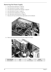
See "Removing the Side Panel" on page 31. 3. See "Removing the Front Bezel" on page 30. 2. Disconnect the 4-pin and 24-pin power supply cables from the mainboard. 8. Screw (Quantity) #6-32 L6 BZN (1) Color Silver Torque 5.7 to the chassis. See "Removing the Processor" on page 34. 6. See "Removing .... 5. See "Removing the Heat Sink Fan Assembly" on page 37. 7. See "Removing the Hard Disk Drive" on page 32. 4. Remove the screw (D) that secures the power supply to 6.3 kgf-cm Part No. 86.00J44.C60 38 Chapter 3 Removing the...
See "Removing the Side Panel" on page 31. 3. See "Removing the Front Bezel" on page 30. 2. Disconnect the 4-pin and 24-pin power supply cables from the mainboard. 8. Screw (Quantity) #6-32 L6 BZN (1) Color Silver Torque 5.7 to the chassis. See "Removing the Processor" on page 34. 6. See "Removing .... 5. See "Removing the Heat Sink Fan Assembly" on page 37. 7. See "Removing the Hard Disk Drive" on page 32. 4. Remove the screw (D) that secures the power supply to 6.3 kgf-cm Part No. 86.00J44.C60 38 Chapter 3 Removing the...

Service Guide
Page 47
9. Screw (Quantity) #6-32 L5 BZN (3) Color Black 10. Lift the power supply module out of the chassis. Torque 5.5 to the rear panel. Remove the three screws (A) that secure the power supply to 6.5 kgf-cm Part No. 86.00J07.B60 Chapter 3 39
9. Screw (Quantity) #6-32 L5 BZN (3) Color Black 10. Lift the power supply module out of the chassis. Torque 5.5 to the rear panel. Remove the three screws (A) that secure the power supply to 6.5 kgf-cm Part No. 86.00J07.B60 Chapter 3 39

Service Guide
Page 57
Obtain the failing symptoms in this chapter are only intended to test Acer products. Refer to "Power System Check" on page 50 and "Beep Codes" on how to troubleshoot system hardware problems. Hardware Diagnostic Procedure IMPORTANT:The diagnostic tests ...described in as much detail as possible. 2. Chapter 4 49 Verify the symptoms by running the diagnostic tests or repeating the same operation. 3. Non-Acer products, ...
Obtain the failing symptoms in this chapter are only intended to test Acer products. Refer to "Power System Check" on page 50 and "Beep Codes" on how to troubleshoot system hardware problems. Hardware Diagnostic Procedure IMPORTANT:The diagnostic tests ...described in as much detail as possible. 2. Chapter 4 49 Verify the symptoms by running the diagnostic tests or repeating the same operation. 3. Non-Acer products, ...


