Service Guide
Page 12
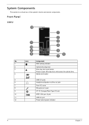
Icon Component 1 HDD activity indicator 2 Optical drive bay door 3 Drive bay door eject button Press to open drive bay door and access the optical drive. 4 Media card reader 5 USB 2.0 ports 6 Headphone/Speaker-out/line-out jack 7 Front I/O cover 8 Microphone-in jack 9 CF I/II (CompactFlash Type I/II) slot 10 IEEE 1394 port (4-pin) 11 USB 2.0 port 12 Power button/power indicator 4 Chapter 1 System Components This section is a virtual tour of the system's interior and exterior components. Front Panel X3812 No.
Icon Component 1 HDD activity indicator 2 Optical drive bay door 3 Drive bay door eject button Press to open drive bay door and access the optical drive. 4 Media card reader 5 USB 2.0 ports 6 Headphone/Speaker-out/line-out jack 7 Front I/O cover 8 Microphone-in jack 9 CF I/II (CompactFlash Type I/II) slot 10 IEEE 1394 port (4-pin) 11 USB 2.0 port 12 Power button/power indicator 4 Chapter 1 System Components This section is a virtual tour of the system's interior and exterior components. Front Panel X3812 No.
Service Guide
Page 13
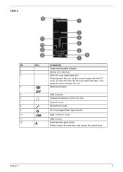
... open the front I /II) slot 10 IEEE 1394 port (4-pin) 11 USB 2.0 port 12 Drive bay door eject button Press to open drive bay door and access the optical drive. Icon Component 1 Power button/power indicator 2 Optical drive bay door 3 Front I/O cover open/close the door, flip the cover back into place, then press...
... open the front I /II) slot 10 IEEE 1394 port (4-pin) 11 USB 2.0 port 12 Drive bay door eject button Press to open drive bay door and access the optical drive. Icon Component 1 Power button/power indicator 2 Optical drive bay door 3 Front I/O cover open/close the door, flip the cover back into place, then press...
Service Guide
Page 33
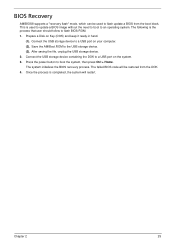
Press the power button to a USB port on your computer. (2). The system initializes the BIOS recovery process. Connect the USB storage device to boot the system, then press Ctrl + ...
Press the power button to a USB port on your computer. (2). The system initializes the BIOS recovery process. Connect the USB storage device to boot the system, then press Ctrl + ...

Service Guide
Page 79
No. 1 2 3 4 5 6 7 8 9 10 11 12 13 14 15 16 17 18 19 20 21 22 23 24 25 26 Part Name C.A LED POWER SWITCH EJECT BUTTON FRONT BEZEL FRONT COVER IO DOOR IO DOOR BKT LENS POWER MAGNET 10*6*3 MIDDLE BEZEL ODD DOOR ODD LINK BKT ODD DOOR SPRING POWER BUTTON PROTECTFILM BEZEL-CVR PROTECTFILM EJECT PROTECTFILM IO DOOR PROTECTFILM MID BZL PROTECTFILM ODD DOOR PROTECTFILM POWER RUB ODD LINK SPG ODD BUTTON BOXER ASSEMBLY L CASE - ASM ASSEMBLY U CASE - ASM FRONT IO BRACKET ODD BRACKET HDD BRACKET Chapter 6 71
No. 1 2 3 4 5 6 7 8 9 10 11 12 13 14 15 16 17 18 19 20 21 22 23 24 25 26 Part Name C.A LED POWER SWITCH EJECT BUTTON FRONT BEZEL FRONT COVER IO DOOR IO DOOR BKT LENS POWER MAGNET 10*6*3 MIDDLE BEZEL ODD DOOR ODD LINK BKT ODD DOOR SPRING POWER BUTTON PROTECTFILM BEZEL-CVR PROTECTFILM EJECT PROTECTFILM IO DOOR PROTECTFILM MID BZL PROTECTFILM ODD DOOR PROTECTFILM POWER RUB ODD LINK SPG ODD BUTTON BOXER ASSEMBLY L CASE - ASM ASSEMBLY U CASE - ASM FRONT IO BRACKET ODD BRACKET HDD BRACKET Chapter 6 71

