Service Guide
Page 7
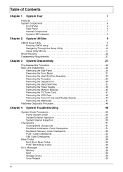
... Heat Sink Fan Assembly 32 Removing the Processor 33 Removing the Optical Drive 34 Removing the Hard Disk Drive 37 Removing the Power Supply 38 Removing the Memory Modules 40 Removing the TV Tuner Card 41 Removing the VGA Card 42 Removing the Front I/O and... Card Reader Boards 44 Removing the Mainboard 47 Hardware Diagnostic Procedure 49 Chapter 4 System Troubleshooting 49 System Check Procedures 50 Power System Check 50 System External Inspection 50 System Internal Inspection 50 Checkpoints 51 Viewing BIOS checkpoints 51 Bootblock Initialization Code Checkpoints 51 ...
... Heat Sink Fan Assembly 32 Removing the Processor 33 Removing the Optical Drive 34 Removing the Hard Disk Drive 37 Removing the Power Supply 38 Removing the Memory Modules 40 Removing the TV Tuner Card 41 Removing the VGA Card 42 Removing the Front I/O and... Card Reader Boards 44 Removing the Mainboard 47 Hardware Diagnostic Procedure 49 Chapter 4 System Troubleshooting 49 System Check Procedures 50 Power System Check 50 System External Inspection 50 System Internal Inspection 50 Checkpoints 51 Viewing BIOS checkpoints 51 Bootblock Initialization Code Checkpoints 51 ...
Service Guide
Page 10
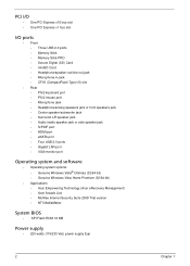
... Vista® Ultimate (32/64-bit) • Genuine Windows Vista Home Premium (32/64-bit) • Applications • Acer Empowering Technology (Acer eRecovery Management) • Acer Arcade Live • McAfee Internet Security Suite 2008 Trial version • NTI MediaMaker System BIOS • SPI Flash ROM 16 MB Power supply • 220-watts (115/230 Vac...
... Vista® Ultimate (32/64-bit) • Genuine Windows Vista Home Premium (32/64-bit) • Applications • Acer Empowering Technology (Acer eRecovery Management) • Acer Arcade Live • McAfee Internet Security Suite 2008 Trial version • NTI MediaMaker System BIOS • SPI Flash ROM 16 MB Power supply • 220-watts (115/230 Vac...

Service Guide
Page 15
Component 1 HDD drive 2 Optical drive 3 Expansion cards 4 Mainboard 5 Heat sink fan assembly 6 Power supply Chapter 1 7 Internal Components No.
Component 1 HDD drive 2 Optical drive 3 Expansion cards 4 Mainboard 5 Heat sink fan assembly 6 Power supply Chapter 1 7 Internal Components No.

Service Guide
Page 37
Main Unit Disassembly MAIN UNIT DISASSEMBLY MAIN UNIT Ax2 SIDE PANEL FRONT BEZEL HEAT SINK FAN ASSEMBLY Bx2 OPTICAL DRIVE CPU Bx2 HDD-ODD BRACKET Ax3, Dx1 POWER SUPPLY Cx4 HDD MODULE HDD MEMORY MODULES Ax1 TV TUNER CARD Ax1 VGA CARD Dx1 FRONT I/O AND CARD READER BOARD BRACKET Dx6 MAINBOARD Dx2 FRONT I/O BOARD Dx2 CARD READER BOARD Screw List A B C D Screw #6-32 L5 BZN M3xL5 BZN #6-32*3/16 NI #6-32 L6 NI Part No. 86.00J07.B60 86.1A324.5R0 86.5A5B6.012 86.00J44.C60 Chapter 3 29
Main Unit Disassembly MAIN UNIT DISASSEMBLY MAIN UNIT Ax2 SIDE PANEL FRONT BEZEL HEAT SINK FAN ASSEMBLY Bx2 OPTICAL DRIVE CPU Bx2 HDD-ODD BRACKET Ax3, Dx1 POWER SUPPLY Cx4 HDD MODULE HDD MEMORY MODULES Ax1 TV TUNER CARD Ax1 VGA CARD Dx1 FRONT I/O AND CARD READER BOARD BRACKET Dx6 MAINBOARD Dx2 FRONT I/O BOARD Dx2 CARD READER BOARD Screw List A B C D Screw #6-32 L5 BZN M3xL5 BZN #6-32*3/16 NI #6-32 L6 NI Part No. 86.00J07.B60 86.1A324.5R0 86.5A5B6.012 86.00J44.C60 Chapter 3 29
Service Guide
Page 46
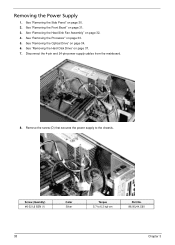
Removing the Power Supply 1. See "Removing the Hard Disk Drive" on page 31. 3. See "Removing the Front Bezel" on page 37. 7. See "Removing the Heat Sink Fan Assembly" on .... 4. Screw (Quantity) #6-32 L6 BZN (1) Color Silver Torque 5.7 to the chassis. See "Removing the Side Panel" on page 33. 5. Disconnect the 4-pin and 24-pin power supply cables from the mainboard. 8. See "Removing the Processor" on page 30. 2. Remove the screw (D) that secures the...
Removing the Power Supply 1. See "Removing the Hard Disk Drive" on page 31. 3. See "Removing the Front Bezel" on page 37. 7. See "Removing the Heat Sink Fan Assembly" on .... 4. Screw (Quantity) #6-32 L6 BZN (1) Color Silver Torque 5.7 to the chassis. See "Removing the Side Panel" on page 33. 5. Disconnect the 4-pin and 24-pin power supply cables from the mainboard. 8. See "Removing the Processor" on page 30. 2. Remove the screw (D) that secures the...

Service Guide
Page 47
Lift the power supply module out of the chassis. Torque 5.5 to the rear panel. 9. Screw (Quantity) #6-32 L5 BZN (3) Color Black 10. Remove the three screws (A) that secure the power supply to 6.5 kgf-cm Part No. 86.00J07.B60 Chapter 3 39
Lift the power supply module out of the chassis. Torque 5.5 to the rear panel. 9. Screw (Quantity) #6-32 L5 BZN (3) Color Black 10. Remove the three screws (A) that secure the power supply to 6.5 kgf-cm Part No. 86.00J07.B60 Chapter 3 39

Service Guide
Page 88
...-5221-08AP-ROHS EUP POWER SUPPLY 220W PFC CPB09-D220A EUP POWER SUPPLY 220W NPFC CPB09-D220R EUP SCRW I NO6-32 L5 BZN SCRW PAN #6-32 L6 NI BOXER WZS SCERW #6-32 L5 PAN NI SCREW PAN M3 L5 BZN SCREW FLAT #6-32*3/16 NI SPEAKER CHIAMAW 9M-20A200-000 ACER LOGO LF 0810 SPEAKER... JAZZ USB2.0 USB MS1238UA Acer Part Number...
...-5221-08AP-ROHS EUP POWER SUPPLY 220W PFC CPB09-D220A EUP POWER SUPPLY 220W NPFC CPB09-D220R EUP SCRW I NO6-32 L5 BZN SCRW PAN #6-32 L6 NI BOXER WZS SCERW #6-32 L5 PAN NI SCREW PAN M3 L5 BZN SCREW FLAT #6-32*3/16 NI SPEAKER CHIAMAW 9M-20A200-000 ACER LOGO LF 0810 SPEAKER... JAZZ USB2.0 USB MS1238UA Acer Part Number...
Service Guide
Page 98
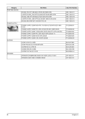
...-220UB A POWER SUPPLY 220W PFC 230V DELTA DPS-220UB-1 A POWER SUPPLY 220W DELTA DPS-220UB POWER SUPPLY 220W LITE-ON DPS-220UB SCRW I NO6-32 L5 BZN SCRW PAN #6-32 L6 NI BOXER WZS SCERW #6-32 L5 PAN NI SCREW PAN M3 L5 BZN SCREW FLAT #6-32*3/16 NI SPEAKER CHIAMAW 9M-20A200-000 ACER LOGO LF... 0810 SPEAKER JAZZ USB2.0 USB MS1238UA Acer Part...
...-220UB A POWER SUPPLY 220W PFC 230V DELTA DPS-220UB-1 A POWER SUPPLY 220W DELTA DPS-220UB POWER SUPPLY 220W LITE-ON DPS-220UB SCRW I NO6-32 L5 BZN SCRW PAN #6-32 L6 NI BOXER WZS SCERW #6-32 L5 PAN NI SCREW PAN M3 L5 BZN SCREW FLAT #6-32*3/16 NI SPEAKER CHIAMAW 9M-20A200-000 ACER LOGO LF... 0810 SPEAKER JAZZ USB2.0 USB MS1238UA Acer Part...


