
Acer V5-471 Notebook Service Guide
Page 6
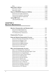
... CHAPTER 3 Machine Maintenance Machine Disassembly and Replacement 3-5 Recommended Equipment 3-5 Replacement Requirements 3-5 Pre-disassembly Instructions 3-6 Disassembly Process 3-7 External Module Disassembly Process 3-8 External Modules Disassembly Flowchart 3-8 Removing the Battery Pack 3-9 Removing the DIMM Cover 3-10 Removing the DIMM Modules 3-11 Removing the ODD Module 3-12 Removing the Keyboard 3-15 Main Unit Disassembly Process 3-17 Main...
... CHAPTER 3 Machine Maintenance Machine Disassembly and Replacement 3-5 Recommended Equipment 3-5 Replacement Requirements 3-5 Pre-disassembly Instructions 3-6 Disassembly Process 3-7 External Module Disassembly Process 3-8 External Modules Disassembly Flowchart 3-8 Removing the Battery Pack 3-9 Removing the DIMM Cover 3-10 Removing the DIMM Modules 3-11 Removing the ODD Module 3-12 Removing the Keyboard 3-15 Main Unit Disassembly Process 3-17 Main...
Acer V5-471 Notebook Service Guide
Page 205
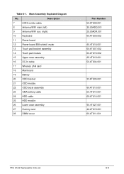
Main Assembly Exploded Diagram No. Table 6-1. Description 7 LVDS combo cable 8 Antenna WIFI main (left) 9 Antenna WIFI aux. (right) 10 Keyboard 11 Power board 12 Power board EMI shield / mylar 13 Touch pad bracket assembly 14 Touch pad module 15 Upper case assembly 16 DC-In cable 17 Wireless LAN card 18 Mainboard 19....4TU04.001 33.4TU05.001 60.4TU10.001 50.4TU14.001 65.4TU14.001 60.4TU27.001 42.4TU15.001 60.4TU11.001 FRU (Field Replaceable Unit) List 6-5
Main Assembly Exploded Diagram No. Table 6-1. Description 7 LVDS combo cable 8 Antenna WIFI main (left) 9 Antenna WIFI aux. (right) 10 Keyboard 11 Power board 12 Power board EMI shield / mylar 13 Touch pad bracket assembly 14 Touch pad module 15 Upper case assembly 16 DC-In cable 17 Wireless LAN card 18 Mainboard 19....4TU04.001 33.4TU05.001 60.4TU10.001 50.4TU14.001 65.4TU14.001 60.4TU27.001 42.4TU15.001 60.4TU11.001 FRU (Field Replaceable Unit) List 6-5


