Aspire T650/E500 and Power F5 Service Guide
Page 1
for more information, please refer to http://csd.acer.com.tw PRINTED IN TAIWAN Aspire T650/E500 AcerPower F5 Service Guide Service guide files and updates are available on the AIPG/CSD web;
for more information, please refer to http://csd.acer.com.tw PRINTED IN TAIWAN Aspire T650/E500 AcerPower F5 Service Guide Service guide files and updates are available on the AIPG/CSD web;

Aspire T650/E500 and Power F5 Service Guide
Page 2
Date Chapter Updates II Revision History Please refer to the table below for the updates made on Aspire T650/E500 and AcerPower F5 service guide.
Date Chapter Updates II Revision History Please refer to the table below for the updates made on Aspire T650/E500 and AcerPower F5 service guide.

Aspire T650/E500 and Power F5 Service Guide
Page 3
...means, electronic, mechanical, magnetic, optical, chemical, manual or otherwise, without notice. Disclaimer The information in any form or by Acer Incorporated. Any Acer Incorporated software described in this publication may be reproduced, transmitted, transcribed, stored in a retrieval system, or translated into any particular... purpose. Intel is a registered trademark of Intel Corporation. Other brand and product names are trademarks of Acer Corporation. III No part of this manual is sold or licensed "as is subject to the contents hereof and specifically...
...means, electronic, mechanical, magnetic, optical, chemical, manual or otherwise, without notice. Disclaimer The information in any form or by Acer Incorporated. Any Acer Incorporated software described in this publication may be reproduced, transmitted, transcribed, stored in a retrieval system, or translated into any particular... purpose. Intel is a registered trademark of Intel Corporation. Other brand and product names are trademarks of Acer Corporation. III No part of this manual is sold or licensed "as is subject to the contents hereof and specifically...

Aspire T650/E500 and Power F5 Service Guide
Page 4
Alerts you to do specific actions relevant to the current topic. NOTE WARNING CAUTION IMPORTANT Gives bits and pieces of additional information related to the accomplishment of procedures. IV Gives precautionary measures to avoid possible hardware or software problems. Reminds you to any damage that appear on screen. Conventions The following conventions are used in this manual: SCREEN MESSAGES Denotes actual messages that might result from doing or not doing specific actions.
Alerts you to do specific actions relevant to the current topic. NOTE WARNING CAUTION IMPORTANT Gives bits and pieces of additional information related to the accomplishment of procedures. IV Gives precautionary measures to avoid possible hardware or software problems. Reminds you to any damage that appear on screen. Conventions The following conventions are used in this manual: SCREEN MESSAGES Denotes actual messages that might result from doing or not doing specific actions.

Aspire T650/E500 and Power F5 Service Guide
Page 5
...to those given in the FRU list of this printed Service Guide. In such cases, please contact your regional Acer office to the BASIC CONFIGURATION decided for Acer's "global" product offering. You MUST use the list provided by your regional offices or the responsible personnel/... number change is made, it supports, please read the following general information. 1. For ACER-AUTHORIZED SERVICE PROVIDERS, your regional web or channel. If, for repair and service of a machine (e.g. add-on your Acer office may have decided to -date information available on card, modem, or extra memory...
...to those given in the FRU list of this printed Service Guide. In such cases, please contact your regional Acer office to the BASIC CONFIGURATION decided for Acer's "global" product offering. You MUST use the list provided by your regional offices or the responsible personnel/... number change is made, it supports, please read the following general information. 1. For ACER-AUTHORIZED SERVICE PROVIDERS, your regional web or channel. If, for repair and service of a machine (e.g. add-on your Acer office may have decided to -date information available on card, modem, or extra memory...
Aspire T650/E500 and Power F5 Service Guide
Page 6
... Connector Setting 11 Connector Information 12 Aspire T650 Front Panel 17 Aspire E500 Front Pane 18 AcerPower F5 Front Panel 19 Aspire T650/E500, AcerPower F5 Rear Panel 20 System Peripherals 21 Acer eRecovery 23 Acer disc-to-disc recovery 25 Hardware Specifications...Machine Disassembly and Replacement 55 General Information 56 Disassembly Procedure 57 Aspire T650 Standard Disassembly Procedure 58 Aspire T650 Standard Reassembly Procedure 66 Aspire E500 Standard Disassembly Procedure 75 Aspire E500 Standard Reassembly Procedure 83 AcerPower F5 Standard Disassembly Procedure 92...
... Connector Setting 11 Connector Information 12 Aspire T650 Front Panel 17 Aspire E500 Front Pane 18 AcerPower F5 Front Panel 19 Aspire T650/E500, AcerPower F5 Rear Panel 20 System Peripherals 21 Acer eRecovery 23 Acer disc-to-disc recovery 25 Hardware Specifications...Machine Disassembly and Replacement 55 General Information 56 Disassembly Procedure 57 Aspire T650 Standard Disassembly Procedure 58 Aspire T650 Standard Reassembly Procedure 66 Aspire E500 Standard Disassembly Procedure 75 Aspire E500 Standard Reassembly Procedure 83 AcerPower F5 Standard Disassembly Procedure 92...
Aspire T650/E500 and Power F5 Service Guide
Page 8
...Express VGA card provides extra graphic solution for extensive gamers T DDR II memory with dual channel provides faster processing speed and efficiency Aspire T650/E500 will be the product name for consumer market. LGA stands forLand Grid Array and means that be the product name for ...Indirect Vertices in Vertex Walker T Full DirectX 9.0 support(Vertex Shader version 2.0 and Pixel shader version 2.0) Chapter 1 1 These two models (Aspire T650/E500 & AcerPower F5) use ATI on the bottom of LGA775 type. Please refer below table for more details address toward each chipset that there...
...Express VGA card provides extra graphic solution for extensive gamers T DDR II memory with dual channel provides faster processing speed and efficiency Aspire T650/E500 will be the product name for consumer market. LGA stands forLand Grid Array and means that be the product name for ...Indirect Vertices in Vertex Walker T Full DirectX 9.0 support(Vertex Shader version 2.0 and Pixel shader version 2.0) Chapter 1 1 These two models (Aspire T650/E500 & AcerPower F5) use ATI on the bottom of LGA775 type. Please refer below table for more details address toward each chipset that there...

Aspire T650/E500 and Power F5 Service Guide
Page 9
Chipset ULI M1573 REALTEK ALC880 Controller Marvell 8EE8001 GigaLAN ITE IT8712 Controller 2 General Features T Provides a High Integration Bridge T One EHCI USB 2.0 and three OHCI USB 1.1 Host Controllers for supporting up to eight USB ports T Supports HS (480Mbits/sec), FS (12Mbits/sec) and LS (1.5Mbits/sec) data transfer rate T Provides High Definition(HD) Audio/AC'97 2.3 compliant digital controller interface for third parties (such as the AMC Codec's vendor) to enable the software modem solution T Provides 1/10/100 Mbps Medium Access Control (MAC) controller for the best solution of the ...
Chipset ULI M1573 REALTEK ALC880 Controller Marvell 8EE8001 GigaLAN ITE IT8712 Controller 2 General Features T Provides a High Integration Bridge T One EHCI USB 2.0 and three OHCI USB 1.1 Host Controllers for supporting up to eight USB ports T Supports HS (480Mbits/sec), FS (12Mbits/sec) and LS (1.5Mbits/sec) data transfer rate T Provides High Definition(HD) Audio/AC'97 2.3 compliant digital controller interface for third parties (such as the AMC Codec's vendor) to enable the software modem solution T Provides 1/10/100 Mbps Medium Access Control (MAC) controller for the best solution of the ...
Aspire T650/E500 and Power F5 Service Guide
Page 10
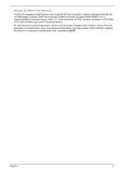
Remark: ULI M1573 ( for an expensive 3rd party audio card. (copyright by OCW) Chapter 1 3 Of most interest in the HD Audio feature, which is very advanced. Essentially, it provides superior Audio Onboard, negating the need for reference) The M1573 integrates a High Definition (HD) Audio/AC'97 Host Controller, 2-channel dedicated Ultra-66/100/ 133 IDE Master controller, SATA Host Controller (4 SATA ports that can support SATA RAID 0,1,0+1) supporting Native Command Queue, USB 2.0/1.1 Host controllers, IO APIC controller, as well as 1/10/100 Mb/ s Fast Ethernet MAC layer and PCI Express ...
Remark: ULI M1573 ( for an expensive 3rd party audio card. (copyright by OCW) Chapter 1 3 Of most interest in the HD Audio feature, which is very advanced. Essentially, it provides superior Audio Onboard, negating the need for reference) The M1573 integrates a High Definition (HD) Audio/AC'97 Host Controller, 2-channel dedicated Ultra-66/100/ 133 IDE Master controller, SATA Host Controller (4 SATA ports that can support SATA RAID 0,1,0+1) supporting Native Command Queue, USB 2.0/1.1 Host controllers, IO APIC controller, as well as 1/10/100 Mb/ s Fast Ethernet MAC layer and PCI Express ...
Aspire T650/E500 and Power F5 Service Guide
Page 12
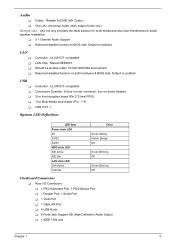
Default is enabled USB T T T T T Controller : ULI M1573 compatible Connectors Quantity : 8 (four on rear connector, four on-board header) 2 for front daughter board (Pin:2*5 Intel FPIO) 1 for audio speaker installation. LAN T T T T Controller : ULI M1573 compatible LAN Chip : Marvell 8EE8001 Should be worked under 10/100/1000 Mbs environment Reserved disabled function on BIOS side. Default is enabled. Audio T Codec : Realtek ALC880 (HD Codec) T One UAJ (Universal Audio Jack) support (rear only) Remark UAJ : UAJ not only provides the ideal solution for multi-media and also user-...
Default is enabled USB T T T T T Controller : ULI M1573 compatible Connectors Quantity : 8 (four on rear connector, four on-board header) 2 for front daughter board (Pin:2*5 Intel FPIO) 1 for audio speaker installation. LAN T T T T Controller : ULI M1573 compatible LAN Chip : Marvell 8EE8001 Should be worked under 10/100/1000 Mbs environment Reserved disabled function on BIOS side. Default is enabled. Audio T Codec : Realtek ALC880 (HD Codec) T One UAJ (Universal Audio Jack) support (rear only) Remark UAJ : UAJ not only provides the ideal solution for multi-media and also user-...
Aspire T650/E500 and Power F5 Service Guide
Page 13
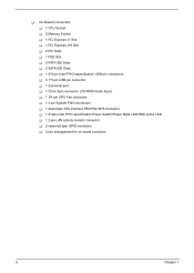
T On-Board Connectors T 1 CPU Socket T 2 Memory Socket T 1 PCI Express x1 Slot T 1 PCI Express x16 Slot T 2 PCI Slots T 1 FDD Slot T 2 PATA IDE Slots T 2 SATA IDE Slots T 1 2*5 pin Intel FPIO sepecification USB pin connectors T 3 1*5 pin USB pin connector T 1 2nd serial port T 1 CD-In 4pin connector (CD-ROM Audio Input) T 1 3/4 pin CPU Fan connector T 1 3 pin System FAN connectors T 1 24pin/4pin ATX interface PS3/PS2 SPS connector T 1 2*4pin Intel FPIO specification Power Switch/Power State LED/HDD active LED T 1 2 pin LAN activity monitor connector T 2 reserved 2pin GPIO connector T Color ...
T On-Board Connectors T 1 CPU Socket T 2 Memory Socket T 1 PCI Express x1 Slot T 1 PCI Express x16 Slot T 2 PCI Slots T 1 FDD Slot T 2 PATA IDE Slots T 2 SATA IDE Slots T 1 2*5 pin Intel FPIO sepecification USB pin connectors T 3 1*5 pin USB pin connector T 1 2nd serial port T 1 CD-In 4pin connector (CD-ROM Audio Input) T 1 3/4 pin CPU Fan connector T 1 3 pin System FAN connectors T 1 24pin/4pin ATX interface PS3/PS2 SPS connector T 1 2*4pin Intel FPIO specification Power Switch/Power State LED/HDD active LED T 1 2 pin LAN activity monitor connector T 2 reserved 2pin GPIO connector T Color ...

Aspire T650/E500 and Power F5 Service Guide
Page 15
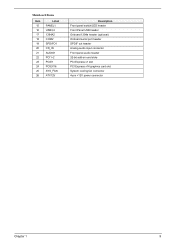
MainBoard Placement Mainboard Items Item 1 2 3 4 5 6 7 8 9 10 11 12 13 14 Label CPU Socket DIMM1,2 IR1 CPU_FAN ATX_POWER BIOS_TBL BIOS_WP FDD IDE2 IDE1 TBD CLR_CMOS SATA1~4 CASE_FAN Description LGA775 socket for Pentium 4 CPUs 240-pin DDR2 SDRAM slots Infrared header CPU cooling fan connector Standard 24-pin ATX power connector BIOS Prevent header BIOS protection jumper Floppy diskette drive connector Secondary IDE channel Primary IDE channel TBD Clear CMOS jumper Serial ATA connectors Case cooling fan connector 8 Chapter 1
MainBoard Placement Mainboard Items Item 1 2 3 4 5 6 7 8 9 10 11 12 13 14 Label CPU Socket DIMM1,2 IR1 CPU_FAN ATX_POWER BIOS_TBL BIOS_WP FDD IDE2 IDE1 TBD CLR_CMOS SATA1~4 CASE_FAN Description LGA775 socket for Pentium 4 CPUs 240-pin DDR2 SDRAM slots Infrared header CPU cooling fan connector Standard 24-pin ATX power connector BIOS Prevent header BIOS protection jumper Floppy diskette drive connector Secondary IDE channel Primary IDE channel TBD Clear CMOS jumper Serial ATA connectors Case cooling fan connector 8 Chapter 1
Aspire T650/E500 and Power F5 Service Guide
Page 16
Mainboard Items Item 15 16 17 18 19 20 21 22 23 24 25 26 Label PANEL1 USB3,4 1394A2 COM2 SPDIFO1 CD_IN AUDIO1 PCI1~2 PCIE1 PCIEX16 SYS_FAN ATX12V Description Front panel switch/LED header Front Panel USB header Onboard 1394a header (optional) Onboard serial port header SPDIF out header Analog audio input connector Front panel audio header 32-bit add-on card slots PCI Express x1 slot PCI Express x16 graphics card slot System cooling fan connector 4-pin +12V power connector Chapter 1 9
Mainboard Items Item 15 16 17 18 19 20 21 22 23 24 25 26 Label PANEL1 USB3,4 1394A2 COM2 SPDIFO1 CD_IN AUDIO1 PCI1~2 PCIE1 PCIEX16 SYS_FAN ATX12V Description Front panel switch/LED header Front Panel USB header Onboard 1394a header (optional) Onboard serial port header SPDIF out header Analog audio input connector Front panel audio header 32-bit add-on card slots PCI Express x1 slot PCI Express x16 graphics card slot System cooling fan connector 4-pin +12V power connector Chapter 1 9
Aspire T650/E500 and Power F5 Service Guide
Page 17
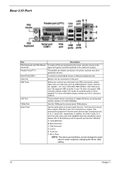
LAN Port The provided Internet connection is for stereo line-in Rear NOTE: The above port definition can be changed to serial-based mouse or data processing devices. In addition, all of a printer, scanner and other peripheral devices. If your device(s) such as USB keyboard, mouse, scanner, zip, speaker...etc. USB Ports Before you connect your device(s) into USB connector(s), please make sure your OS or device(s) vendors. Users please refer to connect audio devices. Rear I/O Port Item Description PS/2 Keyboard and PS/2 Mouse To install a PS/2 port keyboard and ...
LAN Port The provided Internet connection is for stereo line-in Rear NOTE: The above port definition can be changed to serial-based mouse or data processing devices. In addition, all of a printer, scanner and other peripheral devices. If your device(s) such as USB keyboard, mouse, scanner, zip, speaker...etc. USB Ports Before you connect your device(s) into USB connector(s), please make sure your OS or device(s) vendors. Users please refer to connect audio devices. Rear I/O Port Item Description PS/2 Keyboard and PS/2 Mouse To install a PS/2 port keyboard and ...
Aspire T650/E500 and Power F5 Service Guide
Page 18
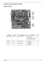
Jumper and Connector Setting Jumper Setting Jumper CLR_CMOS Type 3-pin Description CLEAR CMOS BIOS_WP BIOS_TBL 3-pin 3-pin BIOS PROTECT BIOS PREVENT Setting 1-2: Normal 2-3: Clear CMOS Before clearing the CMOS, make sure to turn off the system. 1-2: DISABLE 2-3: ENABLE 1-2: DISABLE 2-3: ENABLE Chapter 1 11
Jumper and Connector Setting Jumper Setting Jumper CLR_CMOS Type 3-pin Description CLEAR CMOS BIOS_WP BIOS_TBL 3-pin 3-pin BIOS PROTECT BIOS PREVENT Setting 1-2: Normal 2-3: Clear CMOS Before clearing the CMOS, make sure to turn off the system. 1-2: DISABLE 2-3: ENABLE 1-2: DISABLE 2-3: ENABLE Chapter 1 11

Aspire T650/E500 and Power F5 Service Guide
Page 19
Connector Information CPU_FAN/SYS_FAN/CASE FAN Illustration 1 CPU_FAN Pin No. 1 2 3 4 Definition GND +12V Sense Speed Control (Only for CPU Fan) 1 SYS_FAN ATX12V Illustrator 3 4 1 2 PIN No. 1 2 3 4 GND GND +12V +12V Definition 12 Chapter 1
Connector Information CPU_FAN/SYS_FAN/CASE FAN Illustration 1 CPU_FAN Pin No. 1 2 3 4 Definition GND +12V Sense Speed Control (Only for CPU Fan) 1 SYS_FAN ATX12V Illustrator 3 4 1 2 PIN No. 1 2 3 4 GND GND +12V +12V Definition 12 Chapter 1

Aspire T650/E500 and Power F5 Service Guide
Page 20
Definition 13 3.3V 14 -12V 15 GND 16 PS_ON(soft On/Off) 17 GND 18 GND 19 GND 20 -5V 21 +5V 22 +5V 23 +5V 24 GND ATX Power Illustration PIN No. Definition 1 3.3V 2 3.3V 3 GND 4 +5V 5 GND 6 +5V 7 GND 8 Power Good 9 5V SB(stand by +5V) 10 +12V 11 +12V 12 3.3V(Only for 24pins ATX) PIN No. Definition 1 Hard disk LED(+) 2 MSG LED(+) 3 Hard disk LED(-) 4 MSG LED(-) 5 Reset Switch(-) 6 Power Switch(+) 7 Reset Switch(+) PIN No. Definition 8 Power Switch(-) 9 Reserved 10 Key 11 ODD LED(+) 12 LAN LED 13 ODD LED(-) 14 LAN ...
Definition 13 3.3V 14 -12V 15 GND 16 PS_ON(soft On/Off) 17 GND 18 GND 19 GND 20 -5V 21 +5V 22 +5V 23 +5V 24 GND ATX Power Illustration PIN No. Definition 1 3.3V 2 3.3V 3 GND 4 +5V 5 GND 6 +5V 7 GND 8 Power Good 9 5V SB(stand by +5V) 10 +12V 11 +12V 12 3.3V(Only for 24pins ATX) PIN No. Definition 1 Hard disk LED(+) 2 MSG LED(+) 3 Hard disk LED(-) 4 MSG LED(-) 5 Reset Switch(-) 6 Power Switch(+) 7 Reset Switch(+) PIN No. Definition 8 Power Switch(-) 9 Reserved 10 Key 11 ODD LED(+) 12 LAN LED 13 ODD LED(-) 14 LAN ...
Aspire T650/E500 and Power F5 Service Guide
Page 21
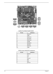
Audio1:Front Panel Audio Header Pin No. 1 2 3 4 5 6 7 8 9 10 Definition PORT-FL GND PORT-FR ACZ-DET PORT-ER AGND SENSE B NO PIN PORT-EL GND SATA1/2/3/4: Serial ATA connectors Pin No. 1 2 3 4 5 6 7 Definition Ground TX+ TXGround RXRX+ Ground 14 Chapter 1
Audio1:Front Panel Audio Header Pin No. 1 2 3 4 5 6 7 8 9 10 Definition PORT-FL GND PORT-FR ACZ-DET PORT-ER AGND SENSE B NO PIN PORT-EL GND SATA1/2/3/4: Serial ATA connectors Pin No. 1 2 3 4 5 6 7 Definition Ground TX+ TXGround RXRX+ Ground 14 Chapter 1

Aspire T650/E500 and Power F5 Service Guide
Page 22
SPDIFO1:SPDIF out header Pin No. 1 2 3 4 Definition 5V analog power No pin SPDIF digital output Ground 1394A2: Onboard IEEE 1394a headers(optional) Pin No. 1 2 3 4 5 6 7 8 9 10 Definition TPA+ TPAGND GND TPB+ TPBCable-Power Cable-Power Key Pin GND USB3/4: Front Panel USB header Pin No. 1 2 3 4 5 6 7 8 9 10 Defintion Power Power USB_FP_P0USB_FP_P1USB_FP_P0+ USB_FP_P1+ GND GND No Pin USB_FP_OC0 (Overcurrent signal) COM2: Onboard serial port header(optional) Pin 1 2 3 4 5 6 Signal Name NDCDB NSINB NSOUTB NDTRB GND NDSRB Definition Data carry detect Serial Data In Serial Data Out Data ...
SPDIFO1:SPDIF out header Pin No. 1 2 3 4 Definition 5V analog power No pin SPDIF digital output Ground 1394A2: Onboard IEEE 1394a headers(optional) Pin No. 1 2 3 4 5 6 7 8 9 10 Definition TPA+ TPAGND GND TPB+ TPBCable-Power Cable-Power Key Pin GND USB3/4: Front Panel USB header Pin No. 1 2 3 4 5 6 7 8 9 10 Defintion Power Power USB_FP_P0USB_FP_P1USB_FP_P0+ USB_FP_P1+ GND GND No Pin USB_FP_OC0 (Overcurrent signal) COM2: Onboard serial port header(optional) Pin 1 2 3 4 5 6 Signal Name NDCDB NSINB NSOUTB NDTRB GND NDSRB Definition Data carry detect Serial Data In Serial Data Out Data ...
Aspire T650/E500 and Power F5 Service Guide
Page 23
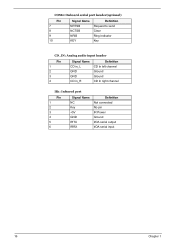
COM2: Onboard serial port header(optional) Pin 7 8 9 10 Signal Name NRTSB NCTSB NRIB KEY Definition Request to send Clear Ring Indicator Key CD_IN: Analog audio input header Pin 1 2 3 4 Signal Name CD in_L GND GND CD in_R Definition CD In left channel Ground Ground CD In right channel IR1: Infrared port Pin 1 2 3 4 5 6 Signal Name NC Key +5V GND IRTX IRRX Definition Not connected No pin IR Power Ground IrDA serial output IrDA serial input 16 Chapter 1
COM2: Onboard serial port header(optional) Pin 7 8 9 10 Signal Name NRTSB NCTSB NRIB KEY Definition Request to send Clear Ring Indicator Key CD_IN: Analog audio input header Pin 1 2 3 4 Signal Name CD in_L GND GND CD in_R Definition CD In left channel Ground Ground CD In right channel IR1: Infrared port Pin 1 2 3 4 5 6 Signal Name NC Key +5V GND IRTX IRRX Definition Not connected No pin IR Power Ground IrDA serial output IrDA serial input 16 Chapter 1