Aspire T180 User's Guide EN
Page 5
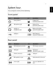
English 1 System tour Your computer consists of the following: Front panel Icon Description Power button Microphone jack Speaker or headphone jack Icon Description Floppy drive (selected models only) Optical drive (selected models only) Media card reader (selected models only) USB port IEEE 1394 port (selected models only) Rear panel Icon Description Icon PS/2 keyboard connector Description PS/2 mouse connector VGA port Printer connector Serial port (selected models only) USB port Microphone-in jack RJ-45 Ethernet connector Line-in jack Line-out / Speaker-out jack
English 1 System tour Your computer consists of the following: Front panel Icon Description Power button Microphone jack Speaker or headphone jack Icon Description Floppy drive (selected models only) Optical drive (selected models only) Media card reader (selected models only) USB port IEEE 1394 port (selected models only) Rear panel Icon Description Icon PS/2 keyboard connector Description PS/2 mouse connector VGA port Printer connector Serial port (selected models only) USB port Microphone-in jack RJ-45 Ethernet connector Line-in jack Line-out / Speaker-out jack
Aspire T180 User's Guide EN
Page 7
English 3 Mouse (PS/2 or USB, manufacturing option) The included mouse is a standard two-button wheel mouse. Note: All images are for reference purposes only. Keyboard (PS/2 or USB, manufacturing option) Connect the keyboard to the PS/2 keyboard port or ...USB port on the back panel of the system. Speakers For systems bundled with speakers, before powering on the system, connect the speaker cable to the PS/2 mouse port or USB port on the back panel of the system. Actual configuration may...
English 3 Mouse (PS/2 or USB, manufacturing option) The included mouse is a standard two-button wheel mouse. Note: All images are for reference purposes only. Keyboard (PS/2 or USB, manufacturing option) Connect the keyboard to the PS/2 keyboard port or ...USB port on the back panel of the system. Speakers For systems bundled with speakers, before powering on the system, connect the speaker cable to the PS/2 mouse port or USB port on the back panel of the system. Actual configuration may...
Aspire T180 User's Guide EN
Page 9
... system. Starting your computer After connecting all the peripheral equipment, start up process is connected, plug the power cord into the system and insert the other end into a power outlet. After the system has shut down your computer according to the steps below: 1 Turn on the...following items are present and in good condition. English 5 Ensure that all peripheral devices. If any of a system crash, press and hold the power button on all peripherals to use your dealer immediately: • AcerPower series • PS/2 or USB keyboard (manufacturing option) • PS/2 or...
... system. Starting your computer After connecting all the peripheral equipment, start up process is connected, plug the power cord into the system and insert the other end into a power outlet. After the system has shut down your computer according to the steps below: 1 Turn on the...following items are present and in good condition. English 5 Ensure that all peripheral devices. If any of a system crash, press and hold the power button on all peripherals to use your dealer immediately: • AcerPower series • PS/2 or USB keyboard (manufacturing option) • PS/2 or...
Aspire E380/T180 - Power M8 Service Guide
Page 14
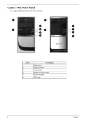
DescriptioLnabel 1 2 3 4 5 6 DNesoc.riptiDonescription Optical drive Floppy disk drive Power button Speaker or headphone jack Microphone jack USB ports 8 Chapter 1 Aspire T180 Front Panel The computer's front panel consists of the following: No.
DescriptioLnabel 1 2 3 4 5 6 DNesoc.riptiDonescription Optical drive Floppy disk drive Power button Speaker or headphone jack Microphone jack USB ports 8 Chapter 1 Aspire T180 Front Panel The computer's front panel consists of the following: No.
Aspire E380/T180 - Power M8 Service Guide
Page 16
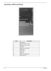
AcerPower M8 Front Panel Label 1 2 3 4 5 6 7 8 9 10 Description Power-Button Speaker-out/Line-out Port Microphone-in out ( Front ) USB Ports Optical drive eject button Optical drive Power LED HDD LED Floppy drive eject button Floppy disk drive 10 Chapter 1
AcerPower M8 Front Panel Label 1 2 3 4 5 6 7 8 9 10 Description Power-Button Speaker-out/Line-out Port Microphone-in out ( Front ) USB Ports Optical drive eject button Optical drive Power LED HDD LED Floppy drive eject button Floppy disk drive 10 Chapter 1

Aspire E380/T180 - Power M8 Service Guide
Page 17
5 4 3 8 2 7 6 1 Label 1 2 3 4 5 6 7 8 Description Power-Button USB ports Microphone-in & Speaker-out/Line-out Port Optical drive eject button Optical drive Indicators Card reader HDD Chapter 1 11
5 4 3 8 2 7 6 1 Label 1 2 3 4 5 6 7 8 Description Power-Button USB ports Microphone-in & Speaker-out/Line-out Port Optical drive eject button Optical drive Indicators Card reader HDD Chapter 1 11
Aspire E380/T180 - Power M8 Service Guide
Page 27
... 90% RH 5 ~ 500 Hz:2.20g RMS random, 10 minutes per axis in all 3 axes 5 ~500 Hz: 1.09g RMS random, 1 hour per axis in all 3 axes Power Management Devices Power Button S1 (Idle) Enabled S3 (Suspend to RAM) Enabled S4 (Suspend to DIsk) Enabled S5 (Shut Down) Disabled Chapter 1 21
... 90% RH 5 ~ 500 Hz:2.20g RMS random, 10 minutes per axis in all 3 axes 5 ~500 Hz: 1.09g RMS random, 1 hour per axis in all 3 axes Power Management Devices Power Button S1 (Idle) Enabled S3 (Suspend to RAM) Enabled S4 (Suspend to DIsk) Enabled S5 (Shut Down) Disabled Chapter 1 21

Aspire E380/T180 - Power M8 Service Guide
Page 29
... T Resume method: Return to original state by pushing external switch button, modem ring in and USB keyboard for ATA standard interface). Suspend Mode T Independent power management timer (2-120 minutes, time step=10 minutes) or pushing external switch button. T Ultra I/O and VGA chip go into Standby mode (for... drive devices (0-15 minutes, time step=1 minute). T Hard disk drive goes into power saving mode. T LED on the panel turns amber colour. T Return to original state by pushing external switch button, modem ring in , keyboard and mouse for APM mode. Chapter 1 23 T ...
... T Resume method: Return to original state by pushing external switch button, modem ring in and USB keyboard for ATA standard interface). Suspend Mode T Independent power management timer (2-120 minutes, time step=10 minutes) or pushing external switch button. T Ultra I/O and VGA chip go into Standby mode (for... drive devices (0-15 minutes, time step=1 minute). T Hard disk drive goes into power saving mode. T LED on the panel turns amber colour. T Return to original state by pushing external switch button, modem ring in , keyboard and mouse for APM mode. Chapter 1 23 T ...
Aspire E380/T180 - Power M8 Service Guide
Page 46
...of time. Disabled Enabled This item enables or disables whether the IDE Disabled hard drive to Instant-Off, then the power button causes a software power down for four seconds to Delay 4 Sec. If the item is set to be resumed by Wake Up Alarms.... to define how your system. This item is not accessed within a specified length of a refresh current to DPMS(Display Power Management Software) by the power button on After Power fail [Enabled] [S1&S3] [User Define] [DPMS Support] [Disabled] [Disabled] [Delay 4 Sec] [Disabled] [Disabled] [Enabled] [Enabled] [Disabled] 0 0 : 0 : 0 [...
...of time. Disabled Enabled This item enables or disables whether the IDE Disabled hard drive to Instant-Off, then the power button causes a software power down for four seconds to Delay 4 Sec. If the item is set to be resumed by Wake Up Alarms.... to define how your system. This item is not accessed within a specified length of a refresh current to DPMS(Display Power Management Software) by the power button on After Power fail [Enabled] [S1&S3] [User Define] [DPMS Support] [Disabled] [Disabled] [Delay 4 Sec] [Disabled] [Disabled] [Enabled] [Enabled] [Disabled] 0 0 : 0 : 0 [...


