Service Guide
Page 7
Table of Contents System Specifications 1 Features 1 System Block Diagram 3 Your Acer Notebook tour 4 Front View 4 Closed Front View 5 Left View 5 Right View 6 Rear View 6 Bottom View 7 Indicators 7 TouchPad Basics 8 Using the Keyboard 9 Lock Keys and embedded ... Removing the Battery Pack 36 Removing the 3G Cover 37 Removing the Keyboard 38 Removing the Upper and Lower Covers 39 LCD Module Disassembly Process 41 LCD Module Disassembly Flowchart 41 Removing the LCD Module 42 Removing the LCD Bezel 44 Removing the Camera Board 45 Removing the MIC Board 46 Removing...
Table of Contents System Specifications 1 Features 1 System Block Diagram 3 Your Acer Notebook tour 4 Front View 4 Closed Front View 5 Left View 5 Right View 6 Rear View 6 Bottom View 7 Indicators 7 TouchPad Basics 8 Using the Keyboard 9 Lock Keys and embedded ... Removing the Battery Pack 36 Removing the 3G Cover 37 Removing the Keyboard 38 Removing the Upper and Lower Covers 39 LCD Module Disassembly Process 41 LCD Module Disassembly Flowchart 41 Removing the LCD Module 42 Removing the LCD Bezel 44 Removing the Camera Board 45 Removing the MIC Board 46 Removing...
Service Guide
Page 43
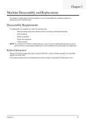
The product previews seen in size. During the disassembly process, group the screws with the corresponding components to disassemble the notebook computer for the different components vary in the disassembly procedures may differ slightly from a SSD SKU. Disassembly Requirements To disassemble the computer, you need the following tools:... using the HDD SKU, unless otherwise specified, and may not represent the final product color. Machine Disassembly and Replacement Chapter 3 This chapter contains step-by-step procedures on how to avoid mismatch when putting back the components.
The product previews seen in size. During the disassembly process, group the screws with the corresponding components to disassemble the notebook computer for the different components vary in the disassembly procedures may differ slightly from a SSD SKU. Disassembly Requirements To disassemble the computer, you need the following tools:... using the HDD SKU, unless otherwise specified, and may not represent the final product color. Machine Disassembly and Replacement Chapter 3 This chapter contains step-by-step procedures on how to avoid mismatch when putting back the components.

Service Guide
Page 44
... the following sections: • Upper cover disassembly • LCD module disassembly • Main unit disassembly The flowcharts provided in that you must first remove the keyboard, then disassemble the inside assembly frame in the succeeding disassembly sections illustrate the entire disassembly sequence. General Information Pre-disassembly Instructions Before proceeding with the disassembly procedure, make sure that order. Observe...
... the following sections: • Upper cover disassembly • LCD module disassembly • Main unit disassembly The flowcharts provided in that you must first remove the keyboard, then disassemble the inside assembly frame in the succeeding disassembly sections illustrate the entire disassembly sequence. General Information Pre-disassembly Instructions Before proceeding with the disassembly procedure, make sure that order. Observe...

Service Guide
Page 45
Tier 1 comprises of the computer. Disassembly is divided into two tiers. Tier 2 incorporates the remaining FRU parts that do not require complete disassembly of FRU parts that require complete disassembly. Screw List Step Upper Cover Screw M2*5 M2*3 (NL) Quantity 5 3 Color Black Black Part No. 86.TG607.004 86.S0207.001 Chapter 3 35 External Module Disassembly Process External Modules Disassembly Flowchart The flowchart below gives you a graphic representation on the entire disassembly sequence and instructs you on the components that need to be removed during servicing.
Tier 1 comprises of the computer. Disassembly is divided into two tiers. Tier 2 incorporates the remaining FRU parts that do not require complete disassembly of FRU parts that require complete disassembly. Screw List Step Upper Cover Screw M2*5 M2*3 (NL) Quantity 5 3 Color Black Black Part No. 86.TG607.004 86.S0207.001 Chapter 3 35 External Module Disassembly Process External Modules Disassembly Flowchart The flowchart below gives you a graphic representation on the entire disassembly sequence and instructs you on the components that need to be removed during servicing.
Service Guide
Page 60
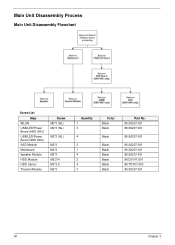
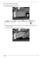
Main Unit Disassembly Process Main Unit Disassembly Flowchart Screw List Step WLAN USB/LED/Power Board (HDD SKU) USB/LED/Power Board (SSD SKU) SSD Module Mainboard Speaker Module HDD Module HDD Carrier Thermal Module Screw M2*3 (NL) M2*3 (NL) M2*3 (NL) M2*3 M2*3 M2*3 M2.5*4 M3*3.5 M2*3 Quantity 1 3 4 2 1 4 2 4 3 Color Black Black Black Black Black Black Black Black Black Part No. 86.S0207.001 86.S0207.001 86.S0207.001 86.S0207.001 86.S0207.001 86.S0207.001 86.D01V7.001 86.TDY07.003 86.S0207.001 50 Chapter 3
Main Unit Disassembly Process Main Unit Disassembly Flowchart Screw List Step WLAN USB/LED/Power Board (HDD SKU) USB/LED/Power Board (SSD SKU) SSD Module Mainboard Speaker Module HDD Module HDD Carrier Thermal Module Screw M2*3 (NL) M2*3 (NL) M2*3 (NL) M2*3 M2*3 M2*3 M2.5*4 M3*3.5 M2*3 Quantity 1 3 4 2 1 4 2 4 3 Color Black Black Black Black Black Black Black Black Black Part No. 86.S0207.001 86.S0207.001 86.S0207.001 86.S0207.001 86.S0207.001 86.S0207.001 86.D01V7.001 86.TDY07.003 86.S0207.001 50 Chapter 3
Service Guide
Page 61
Remove the securing screw as shown. Step WLAN Module Size M2*3 (NL) Quantity 1 Screw Type NOTE: The antenna cables were removed during the LCD module disassembly. Chapter 3 51 See "Removing the Battery Pack" on page 42. 3. The module pops up. See "Removing the LCD Module" on page 36. 2. Remove it from the mainboard as shown. Removing the WLAN Module 1.
Remove the securing screw as shown. Step WLAN Module Size M2*3 (NL) Quantity 1 Screw Type NOTE: The antenna cables were removed during the LCD module disassembly. Chapter 3 51 See "Removing the Battery Pack" on page 42. 3. The module pops up. See "Removing the LCD Module" on page 36. 2. Remove it from the mainboard as shown. Removing the WLAN Module 1.
Service Guide
Page 92
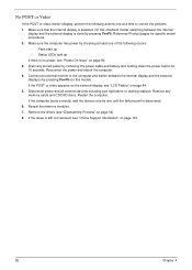
If the POST or video appears on the external display, see "Disassembly Process" on page 161. 82 Chapter 4 Remove any stored power by pressing Fn+F5. Make sure that the internal display is discovered. 6. Reference Product pages .../DVD discs. Disconnect power and all external devices including port replicators or docking stations. Restart the computer. If the computer boots correctly, add the devices one until the failure point is selected. Make sure the computer has power by checking at a time to the computer and switch between the internal display...
If the POST or video appears on the external display, see "Disassembly Process" on page 161. 82 Chapter 4 Remove any stored power by pressing Fn+F5. Make sure that the internal display is discovered. 6. Reference Product pages .../DVD discs. Disconnect power and all external devices including port replicators or docking stations. Restart the computer. If the computer boots correctly, add the devices one until the failure point is selected. Make sure the computer has power by checking at a time to the computer and switch between the internal display...
Service Guide
Page 93
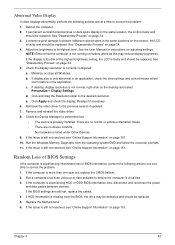
...the display. Random Loss of BIOS information, perform the following actions one at a time to the desired resolution. e. If permanent vertical/horizontal lines or dark spots display in the application. See "Disassembly Process" on adjusting settings. If the computer is faulty and should... be replaced. Chapter 4 83 Abnormal Video Display If video displays abnormally, perform the following actions one year old, replace the CMOS battery. 2. ...
...the display. Random Loss of BIOS information, perform the following actions one at a time to the desired resolution. e. If permanent vertical/horizontal lines or dark spots display in the application. See "Disassembly Process" on adjusting settings. If the computer is faulty and should... be replaced. Chapter 4 83 Abnormal Video Display If video displays abnormally, perform the following actions one year old, replace the CMOS battery. 2. ...
Service Guide
Page 98
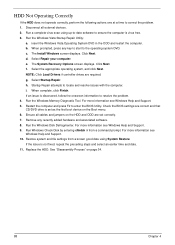
...the problem. 4. For more information see Windows Help and Support. 9. Select Repair your computer. g. Replace the HDD. i. See "Disassembly Process" on the HDD and ODD are required. Run a complete virus scan using System Restore. insert the Windows Vista Operating System DVD...system and file settings from a command prompt. h. HDD Not Operating Correctly If the HDD does not operate correctly, perform the following actions one at a time to enter the BIOS Utility. c. The Install Windows screen displays. Disconnect all cables and jumpers on page 34. 88 Chapter...
...the problem. 4. For more information see Windows Help and Support. 9. Select Repair your computer. g. Replace the HDD. i. See "Disassembly Process" on the HDD and ODD are required. Run a complete virus scan using System Restore. insert the Windows Vista Operating System DVD...system and file settings from a command prompt. h. HDD Not Operating Correctly If the HDD does not operate correctly, perform the following actions one at a time to enter the BIOS Utility. c. The Install Windows screen displays. Disconnect all cables and jumpers on page 34. 88 Chapter...
User Guide
Page 5
.... Do not use it to dangerous voltage points or other controls may interfere with the supplied power supply cord set. Do not pierce, open or disassemble the battery.
.... Do not use it to dangerous voltage points or other controls may interfere with the supplied power supply cord set. Do not pierce, open or disassemble the battery.
User Guide
Page 6
...°F and 77°F). Use the battery only for this device. Batteries may damage the battery or the connecting object. Do not disassemble or dispose of used batteries. Follow local regulations when disposing of them away from the battery, which came bundled with the same type...is fully charged. Keep them in your battery only with a hot or cold battery may explode. Please recycle when possible. Use only Acer approved batteries, and recharge your pocket or purse. Do not dispose of the battery will eventually wear out. Additional safety information Your device...
...°F and 77°F). Use the battery only for this device. Batteries may damage the battery or the connecting object. Do not disassemble or dispose of used batteries. Follow local regulations when disposing of them away from the battery, which came bundled with the same type...is fully charged. Keep them in your battery only with a hot or cold battery may explode. Please recycle when possible. Use only Acer approved batteries, and recharge your pocket or purse. Do not dispose of the battery will eventually wear out. Additional safety information Your device...


