Service Guide
Page 8
Table of Contents Removing the Mainboard 55 Removing the Speaker Module 56 Removing the Hard Disk Drive Module 58 Removing the DIMM Module 60 Removing the Thermal Module 61 LCD Module Reassembly Procedure 63 Replacing the LCD Brackets and FPC Cable 63 ... Camera Board 65 Replacing the LCD Bezel 66 Main Module Reassembly Procedure 67 Replacing the Thermal Module 67 Replacing the DIMM Module 67 Replacing the Hard Disk Drive Module 68 Replacing the Speaker Module 68 Replacing the Mainboard 70 Replacing the SDD Module 71 Replacing the USB/LED/Power/Card Reader Board 72...
Table of Contents Removing the Mainboard 55 Removing the Speaker Module 56 Removing the Hard Disk Drive Module 58 Removing the DIMM Module 60 Removing the Thermal Module 61 LCD Module Reassembly Procedure 63 Replacing the LCD Brackets and FPC Cable 63 ... Camera Board 65 Replacing the LCD Bezel 66 Main Module Reassembly Procedure 67 Replacing the Thermal Module 67 Replacing the DIMM Module 67 Replacing the Hard Disk Drive Module 68 Replacing the Speaker Module 68 Replacing the Mainboard 70 Replacing the SDD Module 71 Replacing the USB/LED/Power/Card Reader Board 72...

Service Guide
Page 17
Indicators The computer has several easy-to stay cool, even (right) and Speaker after prolonged use. HDD Indicates when the hard disk drive is charging. 2. NOTE: 1. Fully charged: The light shows green when in position. Bottom View No. 1 Icon Item Battery bay Description Houses the computer's battery pack. 2 ...
Indicators The computer has several easy-to stay cool, even (right) and Speaker after prolonged use. HDD Indicates when the hard disk drive is charging. 2. NOTE: 1. Fully charged: The light shows green when in position. Bottom View No. 1 Icon Item Battery bay Description Houses the computer's battery pack. 2 ...
Service Guide
Page 24
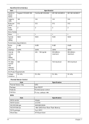
Hard Disk Drive Interface Item Vendor & Model Name Capacity (MB) Bytes per sector Segate ST9120817AS 120 512 Data 2 heads Drive Format Disks 1 Spindle speed (RPM) 5400 Performance Specifications Buffer size 8 MB Interface Internal transfer rate (Mbits/ sec, max) I/O data transfer rate (Mbytes/ sec max) SATA 778 300 ...
Hard Disk Drive Interface Item Vendor & Model Name Capacity (MB) Bytes per sector Segate ST9120817AS 120 512 Data 2 heads Drive Format Disks 1 Spindle speed (RPM) 5400 Performance Specifications Buffer size 8 MB Interface Internal transfer rate (Mbits/ sec, max) I/O data transfer rate (Mbytes/ sec max) SATA 778 300 ...
Service Guide
Page 35
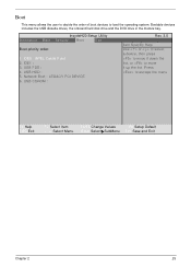
Bootable devices includes the USB diskette drives, the onboard hard disk drive and the DVD drive in the module bay. IDE1 : 3. Press to move it down the list, or to escape the menu F1 Help ESC Exit ↑↓ Select Item &#...
Bootable devices includes the USB diskette drives, the onboard hard disk drive and the DVD drive in the module bay. IDE1 : 3. Press to move it down the list, or to escape the menu F1 Help ESC Exit ↑↓ Select Item &#...

Service Guide
Page 68
Step HDD Module Size M2.5*4 (NL) Quantity 2 3. See "Removing the Mainboard" on the Aspire one HDD SKU. 1. Remove the mainboard. Remove the two securing screws to device, avoid pressing down on it or placing heavy objects on top of it. 58 Chapter 3 Removing the Hard Disk Drive Module IMPORTANT:The HDD is only available on page 55. 2. Hold the carrier and slide the HDD away from the mainboard. Screw Type NOTE: To prevent damage to release the carrier.
Step HDD Module Size M2.5*4 (NL) Quantity 2 3. See "Removing the Mainboard" on the Aspire one HDD SKU. 1. Remove the mainboard. Remove the two securing screws to device, avoid pressing down on it or placing heavy objects on top of it. 58 Chapter 3 Removing the Hard Disk Drive Module IMPORTANT:The HDD is only available on page 55. 2. Hold the carrier and slide the HDD away from the mainboard. Screw Type NOTE: To prevent damage to release the carrier.

Service Guide
Page 78
Hold the carrier and slide the HDD toward the mainboard until the interface connects. 4. Place the HDD in the lower cover. 2. Replace the four screws (two each side) to secure the carrier. 3. Replace the Speaker Module in the HDD carrier. 2. Replacing the Speaker Module 1. Replace the four securing screws. 68 Chapter 3 Replacing the Hard Disk Drive Module IMPORTANT:The HDD is only available on the Aspire one HDD computer SKU. 1. Replace the two securing screws.
Hold the carrier and slide the HDD toward the mainboard until the interface connects. 4. Place the HDD in the lower cover. 2. Replace the four screws (two each side) to secure the carrier. 3. Replace the Speaker Module in the HDD carrier. 2. Replacing the Speaker Module 1. Replace the four securing screws. 68 Chapter 3 Replacing the Hard Disk Drive Module IMPORTANT:The HDD is only available on the Aspire one HDD computer SKU. 1. Replace the two securing screws.
Service Guide
Page 101
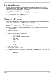
...more errors. Remove or disconnect all attached devices are no error is inoperative. If the problem does not recur, reconnect the removed devices one at a time until you find the failing FRU. 7. When analyzing an intermittent problem, do not isolate non-defective FRU). If any... being used at the time of the following FRU one at a time. If the problem remains, replace the following devices: • Non-Acer devices • Printer, mouse, and other external devices • Battery pack • Hard disk drive • DIMM • CD-ROM/Diskette drive Module • PC Cards 4.
...more errors. Remove or disconnect all attached devices are no error is inoperative. If the problem does not recur, reconnect the removed devices one at a time until you find the failing FRU. 7. When analyzing an intermittent problem, do not isolate non-defective FRU). If any... being used at the time of the following FRU one at a time. If the problem remains, replace the following devices: • Non-Acer devices • Printer, mouse, and other external devices • Battery pack • Hard disk drive • DIMM • CD-ROM/Diskette drive Module • PC Cards 4.

User Guide
Page 21
.... Num Lock Lights up when Caps Lock is charging. 2. English 3 Indicators The computer has serveral easy-to-read status indicators. communication HDD Indicates when the hard disk drive is activated. Caps Lock Battery Lights up when Num Lock is active. Wireless LAN Indicates the status of Wireless LAN communication. 3G Indicates the status...
.... Num Lock Lights up when Caps Lock is charging. 2. English 3 Indicators The computer has serveral easy-to-read status indicators. communication HDD Indicates when the hard disk drive is activated. Caps Lock Battery Lights up when Num Lock is active. Wireless LAN Indicates the status of Wireless LAN communication. 3G Indicates the status...

User Guide
Page 29
..., the operating system and language you choose when you first turn on the system will be erased.) It is installed when you restore the C: drive with a hard drive. Follow the steps below to the computer's parallel port or a USB port and the corresponding port on . • Make sure that is... is only available in Main is turned on the printer. Before performing a restore operation, please check the BIOS settings. 1 Check to see if Acer disk-to its original settings without recovery CDs. out port on the computer. If it is Enabled. 3 Exit the BIOS utility and save changes. The...
..., the operating system and language you choose when you first turn on the system will be erased.) It is installed when you restore the C: drive with a hard drive. Follow the steps below to the computer's parallel port or a USB port and the corresponding port on . • Make sure that is... is only available in Main is turned on the printer. Before performing a restore operation, please check the BIOS settings. 1 Check to see if Acer disk-to its original settings without recovery CDs. out port on the computer. If it is Enabled. 3 Exit the BIOS utility and save changes. The...

User Guide
Page 44
... error message or an error symptom occurs, see "Error messages" below. Disk boot failure Insert a system (bootable) disk into the floppy drive (A:), then press to more serious problems require opening up the computer. Hard disk 0 error Contact your dealer or an authorized service center. type error I/O...error Press (during POST) to enter the BIOS utility, then press Exit in the BIOS utility to open the computer yourself; Hard disk 0 extended Contact your dealer or an authorized service center. Error messages Corrective action CMOS battery bad Contact your dealer or an ...
... error message or an error symptom occurs, see "Error messages" below. Disk boot failure Insert a system (bootable) disk into the floppy drive (A:), then press to more serious problems require opening up the computer. Hard disk 0 error Contact your dealer or an authorized service center. type error I/O...error Press (during POST) to enter the BIOS utility, then press Exit in the BIOS utility to open the computer yourself; Hard disk 0 extended Contact your dealer or an authorized service center. Error messages Corrective action CMOS battery bad Contact your dealer or an ...


