

Service Guide
Page 6
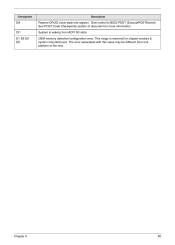
... competitiveness, your regional office MAY have a DIFFERENT part number code to extend the functionality of this generic service guide. For ACER-AUTHORIZED SERVICE PROVIDERS, your regional web or channel. FRU Information Please note WHEN ORDERING FRU PARTS, that you should check the... up-to-date information available on card, modem, or extra memory capability). Service Guide Coverage This Service Guide provides you with further technical details. If, for Acer's "global" product offering. add-on your Acer office may have decided to those given in the printed Service ...
... competitiveness, your regional office MAY have a DIFFERENT part number code to extend the functionality of this generic service guide. For ACER-AUTHORIZED SERVICE PROVIDERS, your regional web or channel. FRU Information Please note WHEN ORDERING FRU PARTS, that you should check the... up-to-date information available on card, modem, or extra memory capability). Service Guide Coverage This Service Guide provides you with further technical details. If, for Acer's "global" product offering. add-on your Acer office may have decided to those given in the printed Service ...
Service Guide
Page 7
... the Front Bezel Removing the Rear USB Board Removing the Cables Removing the System Fan Removing the Optical Drive Removing the Power Supply Removing the Memory Modules Removing the Removable HDD bay Removing the Mainboard 26 26 27 28 29 30 31 32 33 35 36 37 38 39 40 41...
... the Front Bezel Removing the Rear USB Board Removing the Cables Removing the System Fan Removing the Optical Drive Removing the Power Supply Removing the Memory Modules Removing the Removable HDD bay Removing the Mainboard 26 26 27 28 29 30 31 32 33 35 36 37 38 39 40 41...

Service Guide
Page 9
... Lynnfield and Clarkdale platform design guides Should support Intel ASFC Should support Intel PECI • Super I/O: ITE8720 • • PCB • uATX / 244*244mm / 4 Layers Memory subsystem • Socket Type: DDR III connector • • • Socket Quantity: 4 Channel A: slot 0, 1; Channel B: slot 2, 3 Different colors for your reference only...
... Lynnfield and Clarkdale platform design guides Should support Intel ASFC Should support Intel PECI • Super I/O: ITE8720 • • PCB • uATX / 244*244mm / 4 Layers Memory subsystem • Socket Type: DDR III connector • • • Socket Quantity: 4 Channel A: slot 0, 1; Channel B: slot 2, 3 Different colors for your reference only...

Service Guide
Page 10
• • 1GB to 16GB Max memory support Must meet Intel Lynnfield and Clarkdale Chipset platform design guide Design Criteria: • Hard disk • • • Support up to two SATA ports 3.5", ...
• • 1GB to 16GB Max memory support Must meet Intel Lynnfield and Clarkdale Chipset platform design guide Design Criteria: • Hard disk • • • Support up to two SATA ports 3.5", ...

Service Guide
Page 16
...,4G 1GB,2GB,4G 1GB,2GB,4G 1GB,2GB,4G Total Memory 1G ~4GB 1G ~4GB 1G ~4GB 1G ~4GB 1G~16GB Maximum System Memory Supported System Memory Item Memory slot number Support Memory size per socket Support memory type Support memory interface Support memory voltage Support memory module package Support to parity check feature Specification 4 slot 1GB/2GB...
...,4G 1GB,2GB,4G 1GB,2GB,4G 1GB,2GB,4G Total Memory 1G ~4GB 1G ~4GB 1G ~4GB 1G ~4GB 1G~16GB Maximum System Memory Supported System Memory Item Memory slot number Support Memory size per socket Support memory type Support memory interface Support memory voltage Support memory module package Support to parity check feature Specification 4 slot 1GB/2GB...
Service Guide
Page 19
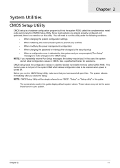
...the same those found in this utility. Ask a qualified technician for assistance. CMOS setup loads the configuration values in CMOS. This memory area is not part of the system RAM which allows configuration data to the CMOS setup NOTE: If you have saved all ...open files. The screenshots used in this case, the system cannot retain configuration values in a battery-backed nonvolatile memory called the complementary metaloxide semiconductor (CMOS) Setup Utility. When changing the system configuration settings When redefining the communication ports to prevent any...
...the same those found in this utility. Ask a qualified technician for assistance. CMOS setup loads the configuration values in CMOS. This memory area is not part of the system RAM which allows configuration data to the CMOS setup NOTE: If you have saved all ...open files. The screenshots used in this case, the system cannot retain configuration values in a battery-backed nonvolatile memory called the complementary metaloxide semiconductor (CMOS) Setup Utility. When changing the system configuration settings When redefining the communication ports to prevent any...
Service Guide
Page 22
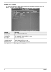
... on the system. Serial number of this system. 14 Chapter 2 Parameter Processor Type Processor Speed System Memory Product Name System Serial Number System BIOS Version BIOS Release Date Asset Tag Number Description Type of the CPU installed on the system. Date when ...
... on the system. Serial number of this system. 14 Chapter 2 Parameter Processor Type Processor Speed System Memory Product Name System Serial Number System BIOS Version BIOS Release Date Asset Tag Number Description Type of the CPU installed on the system. Date when ...

Service Guide
Page 25
...to insert a code in the buffer preventing damage and worm propagation. Enables or disables remapping of overlapped PCI memory above the total physical memory. When disabled, the processor forces the Execute Disable (XD) Bit feature flag to always return to change...Enabled Disabled Intel VT Enables or disables the Virtualization Technology (VT) availability. Select a Video memory size Select a DVMT memory size Enabled Disabled Memory Hole Remapping Video Memory Size DVMT Memory Size Enabled Disabled 32MB 256MB Chapter 2 17 When enabled, the processor disables code execution ...
...to insert a code in the buffer preventing damage and worm propagation. Enables or disables remapping of overlapped PCI memory above the total physical memory. When disabled, the processor forces the Execute Disable (XD) Bit feature flag to always return to change...Enabled Disabled Intel VT Enables or disables the Virtualization Technology (VT) availability. Select a Video memory size Select a DVMT memory size Enabled Disabled Memory Hole Remapping Video Memory Size DVMT Memory Size Enabled Disabled 32MB 256MB Chapter 2 17 When enabled, the processor disables code execution ...

Service Guide
Page 31
Load Default Settings The Load Default Settings menu allows you choose to load the default settings for all BIOS setup parameters. Setup defaults are using low-speed memory chips or other kinds of resources consumption. If you are quite demanding in terms of low-performance components and you to load these settings, the system might not function properly. Chapter 2 23
Load Default Settings The Load Default Settings menu allows you choose to load the default settings for all BIOS setup parameters. Setup defaults are using low-speed memory chips or other kinds of resources consumption. If you are quite demanding in terms of low-performance components and you to load these settings, the system might not function properly. Chapter 2 23

Service Guide
Page 50
Chapter 3 42 Gently pull the DIMM upward to pull it away from the memory board, make sure to release the DIMM. Press the holding clips on both sides of the DIMM slot outward to create a backup file of all important data. 1. 2. Removing the Memory Modules IMPORTANT:Before removing any DIMM from the M/B.
Chapter 3 42 Gently pull the DIMM upward to pull it away from the memory board, make sure to release the DIMM. Press the holding clips on both sides of the DIMM slot outward to create a backup file of all important data. 1. 2. Removing the Memory Modules IMPORTANT:Before removing any DIMM from the M/B.

Service Guide
Page 56
...two short beep Two short beeps Chapter 4 48 In most cases, a checkpoint card is OK. Graphics card error/not installed, graphics card memory error or graphics card BIOS checksum error. CMOS checksum error or CMOS battery loss occurs. Continuous one long beep One long beep and two ...bottom right corner of the screen during POST. System is the best tool for viewing AMIBIOS checkpoints. This display method is ready. Memory not installed or memory error. Not all computers using AMIBIOS enable this feature. Beep codes are used when an error occurs before the system video has...
...two short beep Two short beeps Chapter 4 48 In most cases, a checkpoint card is OK. Graphics card error/not installed, graphics card memory error or graphics card BIOS checksum error. CMOS checksum error or CMOS battery loss occurs. Continuous one long beep One long beep and two ...bottom right corner of the screen during POST. System is the best tool for viewing AMIBIOS checkpoints. This display method is ready. Memory not installed or memory error. Not all computers using AMIBIOS enable this feature. Beep codes are used when an error occurs before the system video has...

Service Guide
Page 57
... value in debugging problems that occur during POST. Go to RAM for faster access. If memory sizing module not executed, start memory refresh and do memory sizing in memory. Verify that may occur during the bootblock initialization portion of the screen during the preboot process... enabled from add-in PCI devices. Early Boot Strap Processor (BSP) initialization like microcode update, frequency and other components before memory detection. NMI is necessary,control flows to execute serial flash. If BIOS recovery is disabled. Do additional chipset initialization. Viewing ...
... value in debugging problems that occur during POST. Go to RAM for faster access. If memory sizing module not executed, start memory refresh and do memory sizing in memory. Verify that may occur during the bootblock initialization portion of the screen during the preboot process... enabled from add-in PCI devices. Early Boot Strap Processor (BSP) initialization like microcode update, frequency and other components before memory detection. NMI is necessary,control flows to execute serial flash. If BIOS recovery is disabled. Do additional chipset initialization. Viewing ...
Service Guide
Page 58
This range is waking from one platform to BIOS POST (ExecutePOSTKernel). The error associated with this value may be different from ACPI S3 state. System is reserved for more information. OEM memory detection/configuration error. Checkpoint Description DA DC E1-E8 ECEE Restore CPUID value back into register. See POST Code Checkpoints section of document for chipset vendors & system manufacturers. Give control to the next. Chapter 4 50
This range is waking from one platform to BIOS POST (ExecutePOSTKernel). The error associated with this value may be different from ACPI S3 state. System is reserved for more information. OEM memory detection/configuration error. Checkpoint Description DA DC E1-E8 ECEE Restore CPUID value back into register. See POST Code Checkpoints section of document for chipset vendors & system manufacturers. Give control to the next. Chapter 4 50

Service Guide
Page 73
Components CPU Model Name or Key Spec. Acer P/N CPU Intel Core i7 870 LGA 2.93G 8M 1333 1156 95W B-1 Quad Core CPU Intel Core i7 860 LGA 2.8G 8M 1333 1156 95W B-1 Quad ... 1333 1156 73W C-2 Dual Core CPU Intel Core i3 530 LGA 2.93G 4M 1333 1156 73W C-2 Dual Core Pentium Dual Core G6950 (2.8G 2M 1066FSB) Memory M378B2873FHS-CH9 LF 128*8 46nm M378B5673FH0-CH9 LF 128*8 46nm GU502203EP0201 LF 128*8 0.065um GU512303EP0202 LF 128*8 0.065um 75.073C1.G02 LF 128*8 0.065um 75...
Components CPU Model Name or Key Spec. Acer P/N CPU Intel Core i7 870 LGA 2.93G 8M 1333 1156 95W B-1 Quad Core CPU Intel Core i7 860 LGA 2.8G 8M 1333 1156 95W B-1 Quad ... 1333 1156 73W C-2 Dual Core CPU Intel Core i3 530 LGA 2.93G 4M 1333 1156 73W C-2 Dual Core Pentium Dual Core G6950 (2.8G 2M 1066FSB) Memory M378B2873FHS-CH9 LF 128*8 46nm M378B5673FH0-CH9 LF 128*8 46nm GU502203EP0201 LF 128*8 0.065um GU512303EP0202 LF 128*8 0.065um 75.073C1.G02 LF 128*8 0.065um 75...


