Acer Desktop User's Guide
Page 3
... to the equipment operator as disconnecting device Observe the following guidelines when connecting and disconnecting power to the power supply unit: Install the power supply unit before connecting the power cord to the equipment, be blocked by unplugging all warnings and instructions marked on an... instructions carefully. CAUTION for future reference. Follow all power cords from the computer. Keep this product from the wall outlet before removing the power supply unit from the power supplies. When you plug the power cord into this product on the product. These openings...
... to the equipment operator as disconnecting device Observe the following guidelines when connecting and disconnecting power to the power supply unit: Install the power supply unit before connecting the power cord to the equipment, be blocked by unplugging all warnings and instructions marked on an... instructions carefully. CAUTION for future reference. Follow all power cords from the computer. Keep this product from the wall outlet before removing the power supply unit from the power supplies. When you plug the power cord into this product on the product. These openings...
Acer Desktop User's Guide
Page 4
... by other nearby electrical devices that is properly grounded before inserting the power supply plug. Contact your dealer or local power company. • Do not allow anything to rest on the power cord. iv do not increase it under sporting, exercising, or any...Safe listening Follow these instructions, suggested by plugging in a grounded power outlet. Using electrical power • This product should not exceed 80% of the power strip's input rating. • This product's power supply is equipped with the performance of power available, consult your electrician for details.
... by other nearby electrical devices that is properly grounded before inserting the power supply plug. Contact your dealer or local power company. • Do not allow anything to rest on the power cord. iv do not increase it under sporting, exercising, or any...Safe listening Follow these instructions, suggested by plugging in a grounded power outlet. Using electrical power • This product should not exceed 80% of the power strip's input rating. • This product's power supply is equipped with the performance of power available, consult your electrician for details.
Acer Desktop User's Guide
Page 5
... for service • the product does not operate normally after following the operating instructions Note: Adjust only those controls that the new power cord meets the following requirements: detachable type, UL listed/CSA certified, type SPT-2, rated 7 A 125 V minimum, VDE approved ... instructions. Unplug this product yourself, as opening or removing covers may expose you need for purchase options. Replace only with the supplied power supply cord set , make sure that are covered by the manufacturer. Telephone line safety • Disconnect all servicing to normal condition....
... for service • the product does not operate normally after following the operating instructions Note: Adjust only those controls that the new power cord meets the following requirements: detachable type, UL listed/CSA certified, type SPT-2, rated 7 A 125 V minimum, VDE approved ... instructions. Unplug this product yourself, as opening or removing covers may expose you need for purchase options. Replace only with the supplied power supply cord set , make sure that are covered by the manufacturer. Telephone line safety • Disconnect all servicing to normal condition....
Service Guide
Page 7
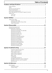
... of Contents Features and Specifications 1 System Features 1 Audio 2 I/O Ports and LED Indicators 2 Physical Specifications 3 Environmental Requirements 3 Power Management Function(ACPI support function 3 System Tour 4 Front View 4 Rear View 5 System Utilities 7 CMOS Setup Utility 7 Entering ...Removing the Removable HDD 39 Removing the Card Reader 43 Removing the Power Supply 46 Removing the Mainboard 48 System Troubleshooting 51 Hardware Diagnostic Procedure 51 System Check Procedures 52 Power System Check 52 System External Inspection 52 System Internal Inspection 52 Beep...
... of Contents Features and Specifications 1 System Features 1 Audio 2 I/O Ports and LED Indicators 2 Physical Specifications 3 Environmental Requirements 3 Power Management Function(ACPI support function 3 System Tour 4 Front View 4 Rear View 5 System Utilities 7 CMOS Setup Utility 7 Entering ...Removing the Removable HDD 39 Removing the Card Reader 43 Removing the Power Supply 46 Removing the Mainboard 48 System Troubleshooting 51 Hardware Diagnostic Procedure 51 System Check Procedures 52 Power System Check 52 System External Inspection 52 System Internal Inspection 52 Beep...
Service Guide
Page 10
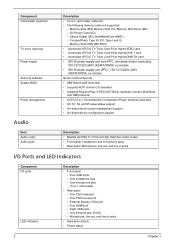
...-C TV Tuner Card PCIe Hybrid DMB-TH card • 300 W power supply unit (non-PFC, non-power factor correction), 100-127V/220-240V (4SATA1PATA) co-module • 300 W power supply unit (PFC), 100-127v/220v-240V (4SATA1PATA) co-module Norton Internet Security • AMI Kernel with Acer skin • Supports ACPI revision 2.0 standard • Supports Plug...
...-C TV Tuner Card PCIe Hybrid DMB-TH card • 300 W power supply unit (non-PFC, non-power factor correction), 100-127V/220-240V (4SATA1PATA) co-module • 300 W power supply unit (PFC), 100-127v/220v-240V (4SATA1PATA) co-module Norton Internet Security • AMI Kernel with Acer skin • Supports ACPI revision 2.0 standard • Supports Plug...

Service Guide
Page 54
Disconnect the cable from the card reader board and remove the card reader board from the bracket. Cut the cable retention strip. NOTE: Make sure you have spare cable retention clips handy, so that you can bundle the cables after replacing the power supply. 46 Chapter 3 Removing the Power Supply 1. c.
Disconnect the cable from the card reader board and remove the card reader board from the bracket. Cut the cable retention strip. NOTE: Make sure you have spare cable retention clips handy, so that you can bundle the cables after replacing the power supply. 46 Chapter 3 Removing the Power Supply 1. c.
Service Guide
Page 55
Remove the four screw that secures the power supply to the chassis. Chapter 3 47 Disconnect the 24-pin and 4-pin power supply cables from the mainboard. 3. 2.
Remove the four screw that secures the power supply to the chassis. Chapter 3 47 Disconnect the 24-pin and 4-pin power supply cables from the mainboard. 3. 2.

Service Guide
Page 56
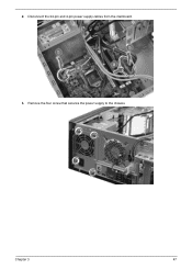
Disconnect the remaining cables from the mainboard. 48 Chapter 3 Lift the power supply module out of the chassis. 4. Removing the Mainboard 1.
Disconnect the remaining cables from the mainboard. 48 Chapter 3 Lift the power supply module out of the chassis. 4. Removing the Mainboard 1.
Service Guide
Page 75
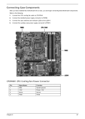
Refer to CPUFAN1. 2. CPUFAN1: CPU Cooling Fan Power Connector Pin Signal Name 1 GND 2 +12V 3 Sense 4 PWM Function System ground Power +12V Sensor PWM Chapter 5 67 Connect the CPU cooling fan cable to the following: 1. Connect the auxiliary case power supply connector to PWR2. 3. Connect the standard power supply connector to PWR1. Connecting Case Components After you have installed the motherboard into a case, you can begin connecting themotherboard components. Connect the case switches and indicator LEDs to the LEDH1. 4.
Refer to CPUFAN1. 2. CPUFAN1: CPU Cooling Fan Power Connector Pin Signal Name 1 GND 2 +12V 3 Sense 4 PWM Function System ground Power +12V Sensor PWM Chapter 5 67 Connect the CPU cooling fan cable to the following: 1. Connect the auxiliary case power supply connector to PWR2. 3. Connect the standard power supply connector to PWR1. Connecting Case Components After you have installed the motherboard into a case, you can begin connecting themotherboard components. Connect the case switches and indicator LEDs to the LEDH1. 4.
Service Guide
Page 78
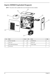
Aspire M3920 Exploded Diagram NOTE: This section will be updated when more information becomes available. No. 1 2 3 4 Item Chassis assembly Top cover Removable HDD Bracket Front cover Qty 1 1 1 No. 5 6 7 Item HDD Bracket Side cover Power supply Qty 1 1 1 70 Chapter 6
Aspire M3920 Exploded Diagram NOTE: This section will be updated when more information becomes available. No. 1 2 3 4 Item Chassis assembly Top cover Removable HDD Bracket Front cover Qty 1 1 1 No. 5 6 7 Item HDD Bracket Side cover Power supply Qty 1 1 1 70 Chapter 6


