
Service Guide
Page 6
...Please note WHEN ORDERING FRU PARTS, that you should check the most up-to-date information available on card, modem, or extra memory capability). For ACER-AUTHORIZED SERVICE PROVIDERS, your regional web or channel. To better fit local market requirements and enhance product competitiveness, your regional offices ...reason, a part number change is made, it will NOT be noted in the printed Service Guide. If, for Acer's "global" product offering. add-on your Acer office may have decided to order FRU parts for repair and service of customer machines. These LOCALIZED FEATURES will not ...
...Please note WHEN ORDERING FRU PARTS, that you should check the most up-to-date information available on card, modem, or extra memory capability). For ACER-AUTHORIZED SERVICE PROVIDERS, your regional web or channel. To better fit local market requirements and enhance product competitiveness, your regional offices ...reason, a part number change is made, it will NOT be noted in the printed Service Guide. If, for Acer's "global" product offering. add-on your Acer office may have decided to order FRU parts for repair and service of customer machines. These LOCALIZED FEATURES will not ...
Service Guide
Page 7
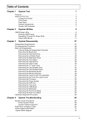
Table of Contents Chapter 1 System Tour 1 Features 1 Aspire G7710 Tour 3 Closed Front Panel 3 Front Panel 4 Rear Panel 5 Internal Components 6 System LED Indicators 7 Chapter 2 System Utilities 9 CMOS Setup Utility 9 Entering CMOS setup 10 Navigating ... Removing the TV Tuner Card 41 Removing the Card Reader Drive 42 Removing the Card Reader Board 44 Removing the Backplane Board 46 Removing the Memory Modules 48 Removing the Liquid Cooler Fan Assembly 49 Removing the Fan from the Liquid Cooler 51 Removing the Processor 52 Removing the Power Supply...
Table of Contents Chapter 1 System Tour 1 Features 1 Aspire G7710 Tour 3 Closed Front Panel 3 Front Panel 4 Rear Panel 5 Internal Components 6 System LED Indicators 7 Chapter 2 System Utilities 9 CMOS Setup Utility 9 Entering CMOS setup 10 Navigating ... Removing the TV Tuner Card 41 Removing the Card Reader Drive 42 Removing the Card Reader Board 44 Removing the Backplane Board 46 Removing the Memory Modules 48 Removing the Liquid Cooler Fan Assembly 49 Removing the Fan from the Liquid Cooler 51 Removing the Processor 52 Removing the Power Supply...
Service Guide
Page 9
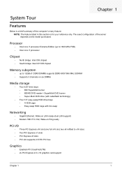
... Extreme Edition (up to 1600 MHz FSB) • Intel core i7 processor Chipset • North bridge: Intel X58 chipset • South bridge: Intel ICH10R chipset Memory subsystem • up to 12GB of the server depends on Ring ready PCI I/O • Three PCI Express x16 slot (one full x16 slot, two x8...
... Extreme Edition (up to 1600 MHz FSB) • Intel core i7 processor Chipset • North bridge: Intel X58 chipset • South bridge: Intel ICH10R chipset Memory subsystem • up to 12GB of the server depends on Ring ready PCI I/O • Three PCI Express x16 slot (one full x16 slot, two x8...

Service Guide
Page 10
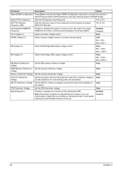
...MMC) • MMCmobile • Reduced-Size MultiMediaCard (RS-MMS) • Secure Digital card • miniSD card • xD-Picture card • Memory Stick • Memory Stick PRO • Memory Stick Duo • Memory Stick PRO Duo • USB 2.0 and IEEE 1394 port I/O ports • Front I/O ports • Fiver USB 2.0 ports • Multi-in-one... DVI-D ports • TV-out port Operating system and software • Operating system options: • Genuine Windows 7 Home Premium (64-bit) • Applications • Acer Empowering Technology (Acer eRecovery Management) 2 Chapter 1
...MMC) • MMCmobile • Reduced-Size MultiMediaCard (RS-MMS) • Secure Digital card • miniSD card • xD-Picture card • Memory Stick • Memory Stick PRO • Memory Stick Duo • Memory Stick PRO Duo • USB 2.0 and IEEE 1394 port I/O ports • Front I/O ports • Fiver USB 2.0 ports • Multi-in-one... DVI-D ports • TV-out port Operating system and software • Operating system options: • Genuine Windows 7 Home Premium (64-bit) • Applications • Acer Empowering Technology (Acer eRecovery Management) 2 Chapter 1

Service Guide
Page 13
Front Panel Item 1 2 3 4 5 6 7 8 9 10 11 12 13 14 Icon Component USB 2.0 ports Microphone/speaker-out/line-in jack Headphone/line-out jack Power button/power indicator Optical disk drives XD (eXtreme Digital) slot USB 2.0 port IEEE 1394 port (4-pin) CFI/II (CompactFlash Type I/II) slot Drive bay door Easy-swap hard disk drives (1-4) MS/MS Pro (Memory Stick/Memory Stick Pro Duo) slot SD/MMC (SecureDigital/MultimediaCard) slot Optical disk drive eject buttons Chapter 1 5
Front Panel Item 1 2 3 4 5 6 7 8 9 10 11 12 13 14 Icon Component USB 2.0 ports Microphone/speaker-out/line-in jack Headphone/line-out jack Power button/power indicator Optical disk drives XD (eXtreme Digital) slot USB 2.0 port IEEE 1394 port (4-pin) CFI/II (CompactFlash Type I/II) slot Drive bay door Easy-swap hard disk drives (1-4) MS/MS Pro (Memory Stick/Memory Stick Pro Duo) slot SD/MMC (SecureDigital/MultimediaCard) slot Optical disk drive eject buttons Chapter 1 5

Service Guide
Page 15
Internal Components Item 1 2 3 4 5 6 7 8 9 10 Component Liquid cooling system Mainboard System memory Release sliders for optical drives Hard drive backplane board Release sliders for HDD drives Expansion slot lock levers Expansion card System fan Power supply module Chapter 1 7
Internal Components Item 1 2 3 4 5 6 7 8 9 10 Component Liquid cooling system Mainboard System memory Release sliders for optical drives Hard drive backplane board Release sliders for HDD drives Expansion slot lock levers Expansion card System fan Power supply module Chapter 1 7

Service Guide
Page 17
... 2 9 CMOS setup loads the configuration values in this guide display default system values. The screenshots used in a battery-backed nonvolatile memory called the complementary metaloxide semiconductor (CMOS) Setup Utility. Before you run the CMOS Setup Utility, make changes to the CMOS setup NOTE...you are already properly configured and optimized, there is a hardware configuration program built into the system ROM, called CMOS RAM. This memory area is not part of the system RAM which allows configuration data to the security setup • When a configuration error is turned off....
... 2 9 CMOS setup loads the configuration values in this guide display default system values. The screenshots used in a battery-backed nonvolatile memory called the complementary metaloxide semiconductor (CMOS) Setup Utility. Before you run the CMOS Setup Utility, make changes to the CMOS setup NOTE...you are already properly configured and optimized, there is a hardware configuration program built into the system ROM, called CMOS RAM. This memory area is not part of the system RAM which allows configuration data to the security setup • When a configuration error is turned off....

Service Guide
Page 21
is necessary. Selects the hard disk drive translation method. Select a DMA (Direct Memory Access) transfer mode to the system. Enables or disables the Self Monitoring Analysis And Reporting Technology (S.M.A.R.T.) capability of device connected to enhance hard disk performance. ...
is necessary. Selects the hard disk drive translation method. Select a DMA (Direct Memory Access) transfer mode to the system. Enables or disables the Self Monitoring Analysis And Reporting Technology (S.M.A.R.T.) capability of device connected to enhance hard disk performance. ...

Service Guide
Page 25
... disables Deep Power off function (deep power off mode reserve only certain power for the CMOS battery and remove other power source such as CPU, memory, WOL function..etc). Enables or disables to wake up the system from a power saving mode through an event on scheduled date/time. Enables or disables...
... disables Deep Power off function (deep power off mode reserve only certain power for the CMOS battery and remove other power source such as CPU, memory, WOL function..etc). Enables or disables to wake up the system from a power saving mode through an event on scheduled date/time. Enables or disables...

Service Guide
Page 27
...effect. Sixth level of overclocking, increases the frequency by 15% Select the Serial Presence Detect (SPD) profile for SLI-Ready memory modules. Any value that 400-1400 MHz is not within this range will restore the default settings instead. First level of...• Sergeant - DOT is not within this 9 function. 6 7 8 19 Frequency Control Parameter D.O.T. Control SLI-Ready Memory System Clock Mode FCB Clock (MHz) Memory Clock (MHz) Adjust CPU Ratio Chapter 2 Description Option Enables or disables Dynamic Overclocking Technology (D.O.T.). DOT detects the load balance of...
...effect. Sixth level of overclocking, increases the frequency by 15% Select the Serial Presence Detect (SPD) profile for SLI-Ready memory modules. Any value that 400-1400 MHz is not within this range will restore the default settings instead. First level of...• Sergeant - DOT is not within this 9 function. 6 7 8 19 Frequency Control Parameter D.O.T. Control SLI-Ready Memory System Clock Mode FCB Clock (MHz) Memory Clock (MHz) Adjust CPU Ratio Chapter 2 Description Option Enables or disables Dynamic Overclocking Technology (D.O.T.). DOT detects the load balance of...
Service Guide
Page 28
...Northbridge (NB) chipset voltage control. Parameter Description Option Adjust DRAM Configuration Press Enter to access the Adjust DRAM Configuration submenu to override the memory's Serial Presence Detect (SPD) settings by manually entering values for overclocking quad-core processors. Enabled Disabled CPU Voltage (V) Select processor voltage ...system to remove (turn off) clocks from empty DIMM and PCI slots to lock up. Auto DIMM Memory Reference Set the memory reference voltage. Note: Remember to Auto provide headroom for DRAM timings. Auto Min: 1.500v Max: 2.000 V NB...
...Northbridge (NB) chipset voltage control. Parameter Description Option Adjust DRAM Configuration Press Enter to access the Adjust DRAM Configuration submenu to override the memory's Serial Presence Detect (SPD) settings by manually entering values for overclocking quad-core processors. Enabled Disabled CPU Voltage (V) Select processor voltage ...system to remove (turn off) clocks from empty DIMM and PCI slots to lock up. Auto DIMM Memory Reference Set the memory reference voltage. Note: Remember to Auto provide headroom for DRAM timings. Auto Min: 1.500v Max: 2.000 V NB...

Service Guide
Page 31
Load Optimized Defaults The Load Optimized Defaults menu allows you choose to load the default settings for all BIOS setup parameters. Chapter 2 23 Setup defaults are using low-speed memory chips or other kinds of resources consumption. If you are quite demanding in terms of low-performance components and you to load these settings, the system might not function properly.
Load Optimized Defaults The Load Optimized Defaults menu allows you choose to load the default settings for all BIOS setup parameters. Chapter 2 23 Setup defaults are using low-speed memory chips or other kinds of resources consumption. If you are quite demanding in terms of low-performance components and you to load these settings, the system might not function properly.
Service Guide
Page 37
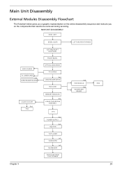
... CARD READER BOARD LIQUID COOLER Fx4 FAN LEFT AND RIGHT SIDE PANEL FRONT BEZEL OPTICAL DISK DRIVE PCI CARDS Bx2 CARD READER DRIVE HDD CAGE MEMORY MODULES Ex4 LIQUID COOLER FAN ASSEMBLY CPU Gx4 POWER SUPPLY Hx4 HDD FAN TOP COVER Ix2 USB BOARD Jx6 MAINBOARD FRONT AND REAR FOOT STANDS...
... CARD READER BOARD LIQUID COOLER Fx4 FAN LEFT AND RIGHT SIDE PANEL FRONT BEZEL OPTICAL DISK DRIVE PCI CARDS Bx2 CARD READER DRIVE HDD CAGE MEMORY MODULES Ex4 LIQUID COOLER FAN ASSEMBLY CPU Gx4 POWER SUPPLY Hx4 HDD FAN TOP COVER Ix2 USB BOARD Jx6 MAINBOARD FRONT AND REAR FOOT STANDS...

Service Guide
Page 56
Press the holding clips on both sides of the DIMM slot outward to create a backup file of all important data. 1. Gently pull the DIMM upward and to pull it away from the memory board, make sure to release the DIMM. 4. See "Removing the Bezel Door" on page 34. 3. Removing the Memory Modules IMPORTANT:Before removing any DIMM from the mainboard. 48 Chapter 3 See "Removing the Left Side Panel" on page 31. 2.
Press the holding clips on both sides of the DIMM slot outward to create a backup file of all important data. 1. Gently pull the DIMM upward and to pull it away from the memory board, make sure to release the DIMM. 4. See "Removing the Bezel Door" on page 34. 3. Removing the Memory Modules IMPORTANT:Before removing any DIMM from the mainboard. 48 Chapter 3 See "Removing the Left Side Panel" on page 31. 2.

Service Guide
Page 60
WARNING:The processor becomes very hot when the system is on page 34. 3. See "Removing the Left Side Panel" on . See "Removing the Memory Modules" on page 31. 2. Removing the Processor IMPORTANT:Before removing a processor from the mainboard, make sure to cool off first before handling. 1. See "Removing the Bezel Door" on page 48. 4. See "Removing the Liquid Cooler Fan Assembly" on page 49. 5. Allow it to create a backup file of all important data. Press down to release load lever. 6. Lift the load lever up and open the load plate. 52 Chapter 3
WARNING:The processor becomes very hot when the system is on page 34. 3. See "Removing the Left Side Panel" on . See "Removing the Memory Modules" on page 31. 2. Removing the Processor IMPORTANT:Before removing a processor from the mainboard, make sure to cool off first before handling. 1. See "Removing the Bezel Door" on page 48. 4. See "Removing the Liquid Cooler Fan Assembly" on page 49. 5. Allow it to create a backup file of all important data. Press down to release load lever. 6. Lift the load lever up and open the load plate. 52 Chapter 3

Service Guide
Page 62
..." on page 46. 9. Disconnect the power supply cables from the retaining clips. 13. See "Removing the Video Cards" on page 48. 10. See "Removing the Memory Modules" on page 39. 6. See "Removing the TV Tuner Card" on page 38. 5. See "Removing the Optical Drive" on page 41. 7. Removing the Power Supply...
..." on page 46. 9. Disconnect the power supply cables from the retaining clips. 13. See "Removing the Video Cards" on page 48. 10. See "Removing the Memory Modules" on page 39. 6. See "Removing the TV Tuner Card" on page 38. 5. See "Removing the Optical Drive" on page 41. 7. Removing the Power Supply...

Service Guide
Page 65
.... 2. See "Removing the Bezel Door" on page 54. 13. See "Removing the Optical Drive" on page 48. 10. Remove the top cover. See "Removing the Memory Modules" on page 38. 5. See "Removing the Front Bezel" on page 42. 8. Chapter 3 57 See "Removing the Card Reader Drive" on page 36. 4. See "Removing...
.... 2. See "Removing the Bezel Door" on page 54. 13. See "Removing the Optical Drive" on page 48. 10. Remove the top cover. See "Removing the Memory Modules" on page 38. 5. See "Removing the Front Bezel" on page 42. 8. Chapter 3 57 See "Removing the Card Reader Drive" on page 36. 4. See "Removing...

Service Guide
Page 66
... audio cables from the mainboard. 13. See "Removing the Optical Drive" on page 41. 5. See "Removing the Backplane Board" on page 48. 8. See "Removing the Memory Modules" on page 46. 7. See "Removing the Processor" on page 52. 10.
... audio cables from the mainboard. 13. See "Removing the Optical Drive" on page 41. 5. See "Removing the Backplane Board" on page 48. 8. See "Removing the Memory Modules" on page 46. 7. See "Removing the Processor" on page 52. 10.

Service Guide
Page 68
... 39. 4. Removing the Mainboard 1. See "Removing the Video Cards" on page 56. 12. See "Removing the Card Reader Drive" on page 48. 8. See "Removing the Memory Modules" on page 42. 6. See "Removing the Processor" on page 54. 11. See "Removing the Power Supply" on page 52. 10. See "Removing the USB...
... 39. 4. Removing the Mainboard 1. See "Removing the Video Cards" on page 56. 12. See "Removing the Card Reader Drive" on page 48. 8. See "Removing the Memory Modules" on page 42. 6. See "Removing the Processor" on page 54. 11. See "Removing the Power Supply" on page 52. 10. See "Removing the USB...
Service Guide
Page 75
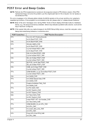
... list, please refer to "Undetermined Problems". If the symptom is not included on the screen and the error symptoms classified by functions. NOTE: Most of memory installed. POST Error and Beep Codes NOTE: Perform the FRU replacement or actions in the sequence shown in FRU/Action column, if the FRU replacement...
... list, please refer to "Undetermined Problems". If the symptom is not included on the screen and the error symptoms classified by functions. NOTE: Most of memory installed. POST Error and Beep Codes NOTE: Perform the FRU replacement or actions in the sequence shown in FRU/Action column, if the FRU replacement...


